By Floyd A. Koontz, WA2WVL
First published in QST (ARRL), January 1996
You’ve seen the basic EWE, now you can have switchable, directional EWEs!
Since the introduction of the EWE antenna in QST, many amateurs have improved their low-band receiving capability with a EWE. [1] In the correspondence I’ve received was a letter from Tony Kazmakites, WB2P, who suggested switching wires above the feedpoint to change directions. This article uses that idea and deals with two switchable configurations of the EWE providing coverage in all directions.
Single EWE for Four Directions
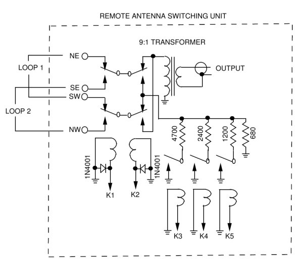
Figure 1 shows a EWE designed to receive in any one of four directions. Relay switching at the base of the central support allows selection of any one of the four wires. As you may remember from the previous article, the back of a EWE is the terminated end, so the relay box is always at the front of the antenna. You select the southwest wire to receive from the northeast. All four wires are anchored to a central square wooden pole and are brought to the bottom of the pole on separate faces (see Figures 2 and 3). The wire opposite the relay box is brought through a small hole near the base of the pole. Wires from the top of the pole are run at 90o from each other, although other angles (or more wires) can be used (see Figure 3). In this design, the terminations are at the bottoms of the outer poles. A 2-kOhm potentiometer mounted in a small diecast aluminum box (Bud CU-123) allowed experimentation, but a fixed-value resistor can be used instead. Figures 4 and 5 show the azimuth and elevation patterns on the single EWE optimized for 160 meters (modeled with the other three antennas in place).
 |
|
Figure 1 – The switchable EWE for 160 meters designed to receive inany one of four directions. Relay switching at the base of the central support (see Figure 3) allows selection of any one of the four wires.
|
 |
|
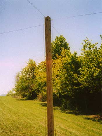
Figure 2 – The center pole of the EWE array. All four antenna wires pass through large eyebolts and descend to the bottom of the pole on separate faces 90o apart from each other. Other angles (and/or more wires) can be used.
|
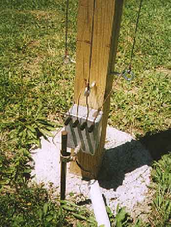 |
| Figure 3 – Near the base of the center pole, an aluminum enclosure houses the four relays. The four wires from the top of the pole are anchored at the pole base in large eye-bolts, one on each face of the pole. Each wire’s bottom end connects to the inside of the relay box through binding posts. From the hidden pole face, the wire passes through a hole drilled in the pole near the eyebolt above the relay box. The feed line approaches the pole through a piece of PVC pipe and is attached to the box via a BNC connector. A ground rod connected to the relay box finishes the installation. |
 |
|
Figure 4 – Azimuth pattern of the 160-meter switchable EWE. |
 |
|
Figure 5 – Elevation pattern of the 160-meter switchable EWE. |
Construction
I’ll describe the construction that I used to build this antenna in an open field. You can stretch the wires out in nearby woods, or tie them to existing support points. All five supports are made of 12-foot-long, 4 x 4-inch pressure-treated timbers. Each pole is set two feet into the ground and anchored using one or two bags of ready-mix concrete (80 to 160 lb). My soil is hard clay. If your antenna farm has sandy or loose soil, a more substantial base may be required. The five poles are oriented so that their sides are parallel to each other. Screw eyes are installed near the top of each pole and about one foot above the ground on each pole, one screw eye on each pole face. There’s one set of screw eyes on each of the outer poles and four sets of screw eyes on the center pole.
I drove 4-foot-long ground rods into the earth near the lower eyes of theouter poles and planted one rod near the relay box on the center pole. In soft soil, longer rods would be appropriate. (If you can easily drive the rod into the ground, it’s not long enough!)
Some EWE-antenna builders who have rocky soil and can’t use ground rods have reported good success using an above-ground return ground wire (counterpoise). Because the feedpoint impedance of this antenna is usually above 400 Ohms and the terminating impedance is generally above 800 Ohms, you can discount the effect of ground resistance.
Relay Box
Four relays are housed in a small diecast aluminum box (Bud CU-234) mounted six inches above ground level (see Figure 3).
The relays are mounted on the box lid along with the connectors and four insulated binding posts. In building an assembly such as this, I line the inside of the box lid with a piece of 1/32-inch-thick, double-sided, copper-clad PC-board. Such material is thin enough to work with BNC bulkhead jacks and provides a solderable ground everywhere. The ground-rod connection is made to the box, which remains fastened to the post should you want to remove the relay assembly for maintenance. Figure 6 shows the relay antenna-switching arrangement. In the future, I plan to control the relays via the coaxial-cable feed line using a serial data stream (I have a 500-foot feed-line run).
Many readers of the first EWE article had questions about the transformer used to match the feedpoint to the feeder. I use a small (about 1/2-inch diameter) core with a permeability of 850 (such as an Amidon FT-50-43) wound with 11 trifilar turns of #26 enameled wire. The turns are connected series-aiding as shown in Figure 6. If you don’t have access to trifilar wire, simply combine three individual strands of enameled wire. [2]
Figure 6 – Diagram of the 160-meter EWE’s relay identifying wire selection. The impedance-matching transformer, T1, matches the antenna feedpoint impedance (about 450 Ohm) to the 50 Ohm coaxial feed line. Make T1 by winding 11 trifilar turns of #26 enameled wire on an Amidon FT-50-43 core. Connect the turns series-aiding, as shown. K1-K4 – SPDT relay, 24-V dc coil, Aromat ARJ322298 or equivalent.
Tuning the EWE
Several EWE builders have attempted to vary the termination resistance to obtain a good impedance match at the input. I don’t recommend this because maximum F/B doesn’t occur coincidentally with the termination value that gives the best match! The EWEs described in this article are terminated with 1.2 kOhm resistors and may display an SWR of up to 2.5. Receiving antennas need not be matched to low SWR values unless they are part of a matched, phased array. Adjust the termination resistance value only while receiving a signal from the rear of the antenna.
Two-Element Array
Later, I placed a second group of five poles 300 feet northeast of the previously described antennas. Figure 7 shows an arrangement of eight EWEs that gives excellent directivity in any of four directions. To the northeast or the southwest, an endfire pattern is produced. A broadside pattern is available to the southeast or northwest. Figures 8 and 9 show the endfire patterns; Figures 10 and 11 show the broadside patterns. For an endfire pattern, the front element is fed through a transformer (T2) to achieve a 180o delay. For a broadside pattern, the two selected elements are fed in phase.
|
|
|
Figure 7 – Here’s how two sets of switchable EWEs (about 300 feet apart) are configured to form a broadside/endfire array. This arrangement of eight EWEs provides excellent directivity in any of four directions. For an endfire pattern, one element is fed through a 180o delay line. For a broadside pattern, the two selected elements are fed in phase. |
|
|
|
Figure 8 – Azimuth pattern of the endfire array. |
|
|
|
Figure 9 – Elevation pattern of the endfire array. |
 |
|
Figure 10 – Azimuth pattern of the broadside array. |
 |
|
Figure 11 – Elevation pattern of the broadside array. |
Array-Relay Switching
Figure 12 shows the switching arrangement I use for selecting northeast endfire, southwest endfire, or the broadside mode. The 180o delay for the endfire mode is produced using a bifilar-wound transformer, T2 (with the center tap grounded). One T2 is required for each direction. T3 has the same basic design of T1, but the feedpoint is tapped up two windings from the ground end.
The relays are shown with K2 energized to produce a northeast endfire pattern. The relay states required for reception in each of the four directions are shown in Table 1.
Figure 12 – Diagram of the phase-switching box used for selecting northeast endfire, southwest endfire, or the broadside mode of the array of Figure 7. The 180o delay for the endfire mode is produced using a bifilar-wound transformer, T2, (with the center tap grounded). One transformer is required for each direction. T3 is made like T1, but the feedpoint of T3 is tapped up two windings from the ground end. The relays are shown with K2 energized to produce a northeast endfire pattern. The relay states required for reception in each of the four directions are shown in Table 1.
Table 1 – Relay States
Relays Energized
| Direction | Group 1 | Group 2 | Array Input Box |
| NE | K1 | K1 | K2 |
| SE | K2 | K2 | – |
| NW | K3 | K3 | K1 |
| SW | K4 | K4 | – |
Summary
With band conditions as they are in the summer, this antenna found only a small amount of use to date. This winter, however, I expect my EWEs to greatly increase my 160-meter operating pleasure!
I’ve shown you two ways to use the EWE element to provide receiving directivity in four or more directions on 160 meters. I’m sure ‘EWE’ will discover many other ways of configuring the EWE. Have fun!
Floyd Koontz, WA2WVL, 6842 Wheeler Rd, Bloomfield, New York, 14469, holds a BSEE in electrical engineering and is currently a Senior Scientist working for Harris Corporation in Rochester, New York. Recently, Floyd has concentrated on the design of directive transmitting and receiving antennas for the 80 and 160-meter bands.
Notes
1 Floyd Koontz, WA2WVL, ‘Is This EWE for You?’ QST, Feb 1995, pages 31 to 33.
2 Use wires of different colors to make identification easy or spot color-code the wires using nail polish or spray paint of different colors. For more information on building various transformers, see Jerry Sevick, W2FMI, Transmission Line Transformers (Newington: ARRL, 1990), 2nd edition. This publication is out of print and no longer available from the ARRL Bookshelf, but a copy may be available at your local library, ham club or from a friend. See also Joseph J. Carr,K4IPV, ‘Make your own RF Transformers,’ Popular Electronics, Nov 1995, pages 67 to 69 and 93.’Ed.