I’ve been getting a lot of e-mail asking about “the published article” on the Pennant and Flag receiving antennas. I get the impression that a rumor has been circulated that an article has be published about the Pennant. Rather than answer each individual query, a posting on the Topband reflector might be better.
There never has been an article published on these antennas. To the best of my knowledge, the only information ever disseminated on them has been what I’ve posted on this Reflector in the past week or so.
Briefly, the Pennant and Flags are in the Ewe family, however, unlike the Ewe, they are independent of any connection to ground.
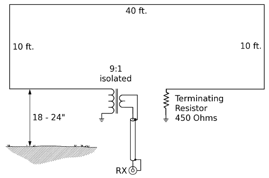
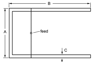
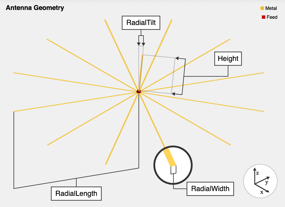
Both the Pennant and the Flag are 14 feet by 29 feet in size. The triangular Pennant was given its name by me because of its shape. The other configuration, being rectangular, I decided to call the “Flag”. All modeling for these antennas was done with the tops of the antennas at 20 feet high and the bottoms at 6 feet high, with all wire #14 gauge.
The correct termination resistor for the Pennant is approximately 900 ohms, which can go either at the point of the Pennant or in the center of the vertical section. The feedpoint is at the opposite end. The correct termination value for the Flag is about 950 ohms, which goes in the center of either vertical section, with the feedpoint in the center of the other vertical section.
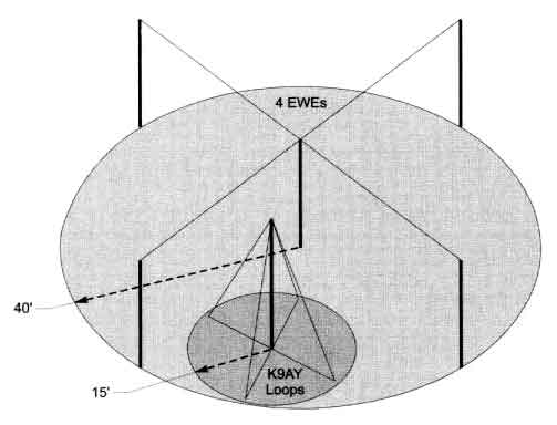
Both antennas are directional with a cardioid azimuth pattern with a deep null to the rear, just like the Ewe. They are useful on 160m, 80m and 40m as a receiving antenna. To my knowledge, only three Pennants are presently in existence: two at K6NDV and one at K6SE. K6NDV also has a K9AY loop installed and he reports that the Pennant is several magnitudes better. The reason for the Pennant and Flag designs was to come up with an Ewe-type of receiving antenna which was as independent of earth ground as possible.
In an effort to overcome the Ewe’s major problem of being so susceptible to underlying soil conductivity, about 6 months ago Jose, EA3VY, designed an antenna he called a “terra-proof Ewe”. He sent me an EZNEC file of the antenna. It was pennant-shaped and was about 13′ by 23′. I noticed that Jose’s antenna had a low amount of reactance on 160m and I started tweaking the antenna size and termination value in an attempt to improve it. The result is what I’ve posted here, but EA3VY certainly deserves credit for being the first to come up with the basic design.
And indeed the Pennant and Flag are “terra-proof”, as Jose calls it.
73, de Earl, K6SE
First published in the TopBand Reflector Aug. 4, 1998 as Pennants and Flags
The Pennant is equilateral triangle-shaped, exactly like a pennant. The vertical side of the Pennant is 14′ long and the upper and lower sloping sides of the Pennant are 29′ 10″ long, meeting at a point 29′ from the vertical section.
The vertical section of my Pennants are 6′ above ground at the bottom and 20′ at the top. The point is at 13′ high and 29′ away from the vertical section. This is exactly how I modeled it.
I feed mine at the point, with the termination resistor (900 ohms) in the center of the vertical section, although it works just as well with the feedpoint and terminations reversed. It receives signals (cardioid pattern) from the direction of the feedpoint end of the antenna, with a deep null in the direction of the terminated end.
A report of your analysis of its common mode Z and balance sensitivity would be most appreciated.
I wound a transmormer using a FT140-43 core per Peter’s suggestion using a 10-turn winding and a 35-turn winding with the windings separated as much as possible on the core. I used a turns ratio of 3.5 because I feed the Pennants with 75-ohm coax, so this would closely match the 900-ohm Z of the Pennant.
After Installing the transformer, tests were made with K6NDV who is 4.5 miles away and in direct line with my Pennants. On 160m, F/B was only 6dB. On 80m, F/B was 45+dB. No check was made on 40m due to Will tx antenna the is horizontally polarized.
We put some snap-on ferrite chokes on both the feedline and the 12-volt wiring to the switching relay at the antenna end of these cables. The Mu of these chokes is unknown, although it did improve the F/B with K6NDV on 160m to 12dB.
Over the last few days I’ve checked the F/B on sky wave signals with F/B as high as 36dB or better on 160, 80 and 40m. It was strange that the F/B on two stations in QSO with each other on 160m in Arizona varied from about one S-unit for one station to six or seven S-units for the other.
This all has been with my 160m and 80m shunt feeds on my towers completely detuned. When the shunt feeds are tuned properly, the Pennant F/B deteriorates to zilch on those two bands. The Pennants are about 70′ from one tower and 22′ from the other. When detuned, the tower structures are 1/4-wave resonant at about 2100 kHz and modeling still shows a very noticeable affect, although nowhere near as bad as when the towers are tuned.
I plan to retune the towers tomorrow so as not to miss out on the DX, hi.
73, de Earl, K6SE
First published in the TopBand Reflector Sep. 24, 1998 as Pennant Report