a compact, directional receiving antenna
by Gary Breed, K9AYfirst published in QST (ARRL), Newington, Sep 1997
Wish you had enough room for an effective low-band receiving antenna? You do! This four-direction system fits in a 30-foot circle!
Low-band operators are always looking for ways to improve their hearing. As a low-band fan, I was impressed with the EWE antenna developed by Floyd Koontz, WA2WVL2. Koontz shows us how to build a compact, directional antenna-a design that quickly became very popular. But when I sat down at the computer to figure out the best way to install my own EWEs, a surprising new design emerged from my modeling experiments.
Ladies and Gentlemen…
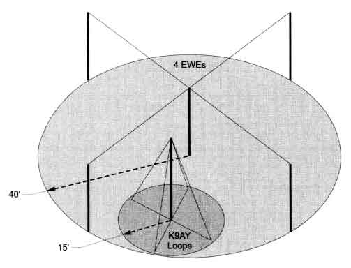
Allow me to introduce you to the terminated loop, a concept that further shrinks the space required for a good receiving antenna without sacrificing performance! Figure 1 compares the real estate requirements of my four-direction loop system to that of an equivalent EWE array. The new system is not only smaller, it’s easier to install, needing only one support instead of five.
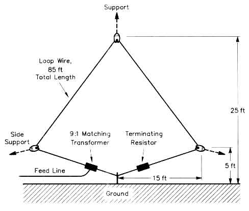
The terminated loop (see Figure 2) is physically and electrically quite simple. It consists of a wire loop of any convenient shape (diamond, delta, etc), hung from a single support and with a ground rod at the bottom. A 9:1 impedance-matching transformer connects from one end of the loop to ground; a terminating resistor connects the other end of the loop to ground. This antenna is directional, favoring signals arriving from the feed point end, rejecting by several S units any signals arriving from the end connected to the terminating resistor, RTERM.
Here’s the real news: A very small terminated loop maintains its directional pattern. As the loop’s size gets smaller, however, the desired signal strength is also reduced. The antenna described here is small enough to fit into a corner of almost any backyard. The loop could be made smaller, but I wanted to collect enough signal energy so that even a modest preamp (such as those included in most HF rigs) can be used. More information on the antenna’s operation can be found in the sidebars “How Does the Terminated Loop Work?” and “Summary of Characteristics.”
 |
|
Figure 1 |
 |
|
Figure 2 |
To cover all directions, two loops using the same support are oriented at right angles to each other. Each loop provides reception from two directions when the feed point and termination are reversed, for a total of four separate patterns. Here are all the details you need to build the K9AY Loop antenna system, including a relay-controlled patternswitching system that uses the coaxial feed line to carry the switching system control voltage.
Let’s Build It!
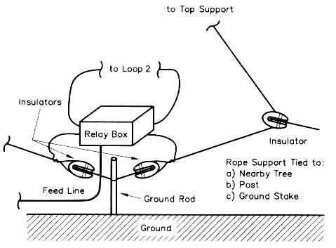 |
| Figure 3 – Construction details of a terminated loop, showing the base connections and corner supports of one of the loops. The relay box also houses the 9:1 matching transformer. |
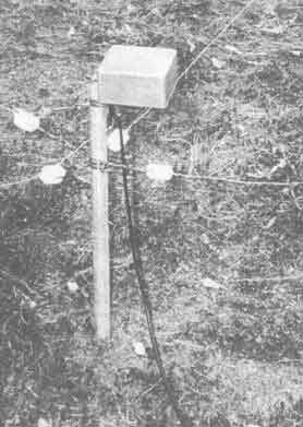 |
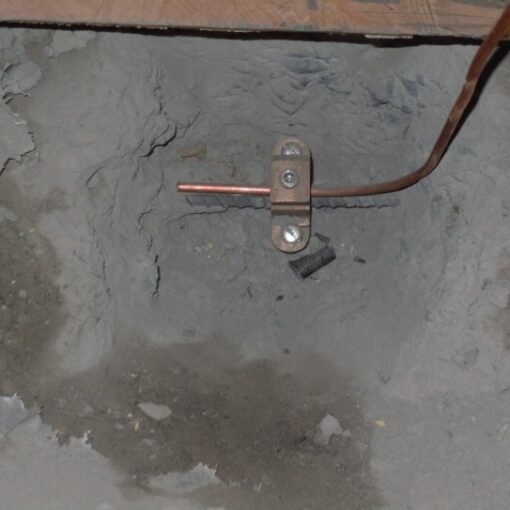
| Figure 4 – A photo of the central connection point at the base of a two-loop system, as installed at K9AY. |
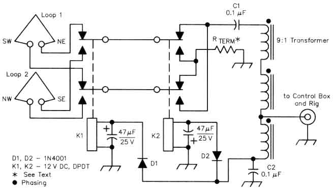 |
| Figure 5 – Schematic of the relay box located at the base of the system. The relays switch between the two loops, reversing the feed point and termination connections. |
First, gather the following materials to construct the loops:
Two lengths of wire about 85 feet each. Although almost any wire size will do, #14 copper is probably the best for a long-lasting installation.
Ten simple insulators – anything from old toothbrush handles to fancy porcelain insulators will do.
A three or four-foot length of copper pipe – the ground rod doesn’t need to be driven deeply-a depth of three to four feet is sufficient. Because copper-plated steel rods eventually rust, I prefer to use 1/2 or 3/4-inch-diameter copper water pipe.
One support 25 feet above groundmy antenna hangs from a limb of a Georgia Pine, but anything that gets the top of the loops up about 25 feet will work. The wooden A frame support described in The ARRL Handbook and Antenna Book is an excellent choice. A metal mast can be used, but make it only as long as necessary and insulate it from ground. Large metal objects affect the antenna’s performance, so install it in the clear. You’ll also need some rope – nothing fancy, just something strong enough to keep things in place.
Now, grab your tools and head for the backyard. Attach the midpoint of each wire length to an insulator that will be positioned at the top of the loop. The two loops must not touch each other, so leave some room between their insulators. I separated my insulators with about a foot of rope.
Aligned directly under the tops of the loops, drive a ground rod, leaving a foot or so above ground as an attachment point. Using short ropes or wires, connect four insulators a few inches away from this post to receive the lower ends of the loops. Leave a foot of wire for a pigtail after twisting the ends of the loop wires around the insulators. Figure 3 sketches the important installation details, and the photo of Figure 4 shows how my system is installed.
The lower corners of the loops are supported by insulators and ropes tied off to nearby trees, fence posts, or stakes driven into the ground. Pull out the corners with enough tension to maintain the loop shapes. At this point, the major mechanical work is finished and you should have something resembling an eggbeater, as shown in Figure 1.
The Relay Box and Controller
Figure 5 shows the relay circuit used to switch the feed and termination points of the loop wires. House the components in a weatherproof box having external conncltion points for the four ends of the loops, a coax connector for the feed line and a groundwire attachment.
K1 is a DPDT relay that switches between the two loops. K2, another DPDT relay, swaps the connections of the terminating resistor and matching transformer, thereby reversing the pattern. Relay power is supplied via the coaxial feed line. C1 keeps the control voltage from reaching the antenna, and C2 provides an RF ground for the transformer.
Most builders will likely choose to orient the loops for northeast/southwest and northwest/southeast directions. The relay box has four switching modes, one for each direction:
1) northeast, when neither relay is energized;
2) southeast, when K1 only is energized;
3) southwest, when K2 only is energized and
4) northwest, when both relays are energized.
Switching is accomplished using a single power connection through steering diodes D1 and D2. D1 allows K1 to operate when + 12 V is applied, while D2 blocks the voltage from reaching K2. When -12 V is applied, K2 operates, but not K1. When 12 V ac is applied, the diodes rectify it to operate both relays.
The matching transformer is a 9:1 impedance, 3:1 turns ratio type that should be familiar to many readers. Five trifilar turns of ordinary hookup wire are wound on a 3/4-inch diameter (0.825 inch) 43 material toroid. The terminating resistor (RTERM) value will be between 390 to 560 W depending on your band preference. With average ground conductivity, a value of 390 W provides the optimum F/B at 160 meters, while 560 W it optimizes the loops for 80 meters. A value of 470 W splits the difference for “pretty good” performance on both bands. I chose to optimize the antenna for 160 meter operation, so used a 390 W resistor. Use an RTERM power rating of at least 1 W in case some transmitter power ends up being coupled to the loops. I use a 2-W carbon resistor, but two parallel 1/2 W or four 1/4 W units of appropriate ohmic value can also be substituted.
Figure 6 is a diagram of the control bus that is located in the shack. One 12 V ac trans former provides the ac relay power and feed, two half-wave rectifiers and filter capacitom, to generate 12 V. One SP4T switch selects the proper voltage to apply to the coax. The RF choke and 0.1 mF capacitor keep the R1 and control voltage separated at the shack end.
Once the control unit and relay box are built and operating properly, mount the relay box at the ground rod and connect the four ends of the loops to their proper terminals. A length of 50 W coax carries the signal and power between the antenna and the switch box in the shack. I highly recommend lying the coax on the ground (buried is better) to minimize pickup of noise or energy coupled from your transmit antenna. A receiving preamplifier is almost certainly needed, either your rig’s internal preamp or an external preamp.
Summary of Characteristics
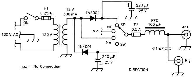 |
| Figure 6 – Schematic of the control box located in the shack. The control voltage to operate the relays is delivered via the coaxial line. |
When choosing a specific configuration or location for your K9AY Loop system, consider this list of characteristics:
Like all antennas, this one can be affected by nearby metallic objects or structures. Do your best to keep the antenna in the clear, away from your tower, house and power lines.
Noise reduction in this antenna is achieved mainly by the directional pattern, although being grounded offers some reduction of wind, rain and snow static. Compared to the typical omnidirectional vertical or low inverted V, the reduction in overall noise and interference can be dramatic.
The maximum circumference of the loop is a little over 1/4 l at the highest frequency of operation. If the loop is larger, the E and H-field responses of the antenna can no longer be balanced. Smaller loops (or same-size loops at lower frequencies) retain the directional pattern, which makes this an excellent antenna for AM broadcast reception. Unfortunately, the received signal voltage is proportional to the area enclosed by the loop, so sensitivity decreases rapidly as the antenna becomes smaller. Unless you have a very good preamp, keep the loop sizes near the maximum.
The T-Loop is not just a low-frequency antenna! It can be used at high frequencies for shortwave listening, or to provide improved reception over an omnidirectional antenna such as a vertical. Just scale the size to the desired frequency using the guidelines presented in the accompanying article.
Evaluation and Adjustment
Next, verify that the antenna is working correctly, Some listening is probably what you’ll do first, but fading makes it almost impossible to determine the antenna’s actual performance. At best, you will be able to confirm that the antenna has reasonable directivity.
More accurate listening tests can be performed several ways. The best way is to enlist the aid of a nearby ham whose station is very close to being in line with one of the two loops. If such help is not available, the next-best option is to identify a local AM radio station high in the band (1400-1600 kHz) and use that as your test signal. Switch the loops to their various directions. If the test station is directly in line with one loop, you should see a frontto-back (F/B) ratio of about 2 to 3 S units as the antenna is switched toward and away from the station. You won’t see a huge F/B because the deepest null is up at 30 to 40 deg.
Local ground conductivity can affect performance. You might not get an optimum pattern at your particular location with the “normal-value” terminating resistor. If you aren’t getting the expected performance, substitute a 1 kW potentiometer for the terminating resistor and adjust it for best F/B while listening to your test station. Then, measure the pot’s resistance and install a fixed-value resistor of the same value.
Antenna Performance
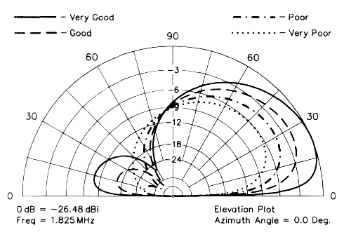
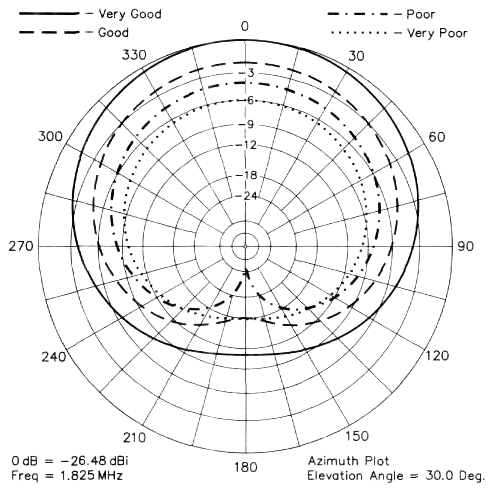
The vertical pattern of the antenna, in line with the loop, is shown in Figure 7. Figure 8 is the azimuth pattern at 30deg elevation. Modeling was done using W7EL’s EZNEC program3 which uses NEC-2 to evaluate the antenna over “real” ground4. Listening tests confirm that these modeled patterns are close to the as-built antenna performance. Much of the on-air pattern evaluation was done by listening to AM broadcast stations and to WWV on 2.5 MHz, because the pattern of the antenna changes little over this frequency range. Stations at exactly the right distance and directions have verified the deep null off the back. For example, New York City area radio stations are exactly in line with my northeast/southwest loop, and show 40 dB F/B ratio when the arrival angle is just right!
The front of the pattern is quite broad, with maybe one S unit F/S. The advantage of this antenna is its rearward null, which reduces local noise and distant QRM. I installed my system just 2 1/2 weeks before the 1996 ARRL 160 Meter Contest, so it got a thorough evaluation in a short time. During the contest, changing the pattern direction often made the difference between Q5 copy and a busted contact. For example, pointing southeast to hear Caribbean stations reduced stateside QRM by 2 or 3 S units, enough to easily hear the DX through unruly pileups.
Higher-Performance Ideas
The compact size of the K9AY Loop makes it easy to build more than one for a multielement array. Installing two of them in a broadside/endfire combination is one option, but a really ambitious approach would be to install a four-square! This array would have a substantial F/B over a wide angle, along with a much narrower front lobe than a single loop. The space required for this highperformance array is far less than what is needed for Beverages. If you try this, remember to switch the individual loops to the desired direction as you switch the feed system.
Summary
If you want improved reception on the low bands and don’t have a lot of room, the terminated loop is an excellent choice. It is small, easy to build and its directional pattern makes DX much easier to hear.
 |
|
Figure 7 – Vertical radiation pattern of the loops along the plane of the loop. |
 |
|
Figure 8 – Horizontal radiation pattern of the loops at 30o elevation. |
Notes
1 Floyd Koontz, WA2WVL, “Is This Ewe for You?” QST, Feb 1995, pp 31-33.2 Floyd Koontz, WA2WVL, “More EWEs for You,” QST, Jan 1996, pp 32-34
3 EZNEC 1.0 by Roy Lewallen, W7EL, PO Box 6658, Beaverton, OR 97007; tel: 503-6462885, fax: 503-671-9046.
4 The modeling accuracy of antennas with a direct connection to ground is somewhat uncertain, even with the power of NEC-2. The high accuracy ground characterization of the Sommerfield method gives answers that vary with the number of segments chosen for each wire. The MININEC-type ground model gives more consistent results, but on-air tests show that the deepest null is obtained with a lower value terminating resistor than this model indicates. The plots presented here are the “best fit” between modeled and observed performance.
Gary Breed has been a ham since the age of 12, and has held the call sign K9AY since 1976. He enjoys contesting, DXing, “homebrewing”, QRP operating and, of course, experimenting with antennas. Gary holds a patent for a multifrequency antenna technique and has provided antennas for the AH1A, 9G1XA, 3Y0PI, V5/ZS6YG and ZL8RI DXpeditions. You can contact Gary at 501 Swanson Dr, Lawrenceville, GA 3
