Mario, S56A, developed many state-of-art SO2R devices. Look at these hi-tech units!
S3O2R – S56A Simple Single Op. Two Radio Interface
by Marijan Miletic, S56A, N1YU
SO2R category is becoming very popular in HF contests. Several PC programs support operation via LPT and COM ports. Commercial switching boxes were recently introduced by two USA manufacturers. ARRL Handbook 2000 has a nice SO2R project by N6BV. N6TR original interface is available on K5TR homepage. It is interesting that everybody stil uses relays for a low level digital or audio signals. Eventual RF interference to IC can be easily controlled by RC networks on these low frequencies!
I made two solid state boxes using pair of MC-1489 for COM ports and 74LS26 for LPT KEY and PTT dual outputs. CMOS mux 4053 IC was used for headphones and microphone switching. Mike is much better controled by Sound Blaster in Windows Writelog program. My simplified CW interface for two radios is shown bellow.
 |
 |
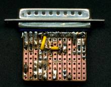 |
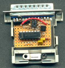
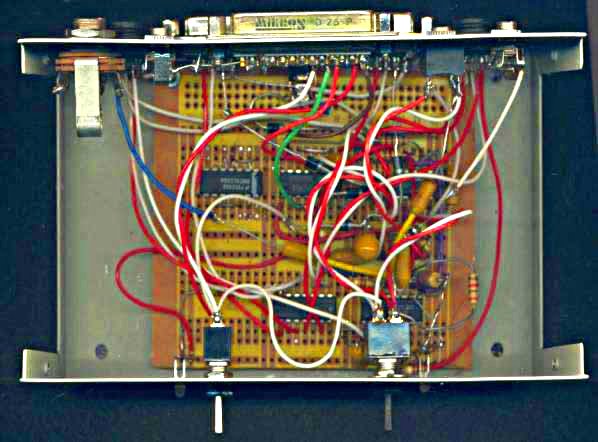
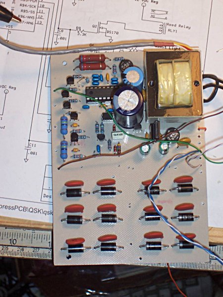
It uses 74LS26 high voltage open colector NAND gates which are specified up to 15 V. Sinking current on modern HF radios is few miliamps only. Port selection is inverted by a single MOS transistor. Integrated network of 5 x 3,3 kOhm resistors is used for FOOT and PADDLE pull-ups. This interface consumes 10 mA on +5V. This is regulated by 78L05 from any DC or AC input voltage higher of 7V. Diode D1 rectifies low voltage AC supply from suitable mains adapter. Note that STROBE signal on LPT pin 1 is NOT used! Pins 18-25 are soldered together and grounded on the external casing via BUSY pin 11. The whole interface fits into the extended DB-25 plastic cover. Two photos of the prototype are shown.
S2O2R – S56A SO2R LPT and COM interface
SO2R PC interfaces can be bought from two USA sources or made according to N6BV project in ARRL 2000 Handbook or N6TR schematics on official K5TR web pages.
All these circuits use relays for low level audio switching and digital keying. This is definitely not the state of the art in the 23rd century. Reliability leaves a lot to be desired…
I initially made simple LPT keying interface S3O2R It uses high voltage 74LS26 NAND IC for dual KEY and PTT control from LPT port. Paddle and foot inputs are also provided.
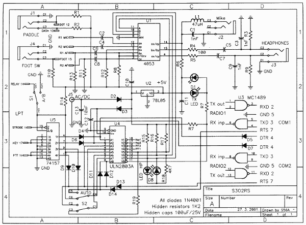
Click here to view or download an enlarged image (2220 x 1639 px.)
The S2O2R cirucit utilises 74LS157 for full decoding of LPT control signals. These are: Strobe on LPT pin 1 used as LS enable, radio A/B on LPT pin 14 for multiplexer direction, PTT-in from LPT 16 for PTT-out control and CW-in on LPT 17 for keying. LS PTT and KEY outputs use diode OR gates to control ULN-2803A Darlington switches. These are well protected and specified for +50V and +500mA. This greatly exceeds the requirements of all modern radios. The other 2830 input signal comes via second pair of diodes from COM ports. DTR is used for keying, RTS for PTT control. Negative RS-232 OFF levels do not affect 2803A operation. TXD and RXD serial signals for radio frequency managment are transfered to TTL levels by MC-1489. I prefer this very old RTL receiver to modern MAXIM 232 types. They are noisy due to switching capacitive converters from +5V to +10V and +10V to -10V for RS-232 TX.
MC-1489 also used as TX here gives more then +3V output required for a proper PC RX operation. Headphones are switched by CMOS 4053 triple SPDT mux. Last mux is auxiliary for Electret mike. Good grounding should be provided between radios in order to avoid audio hum. This is needed for RFI reduction anyway. Prototype PCB is shown below.
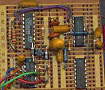 |
This interface nicely fits into the box intended for two printers selection! DB-25M is used for LPT input, other two are replaced with smaller DB-9F for COM ports. Two miniature DIN connector known from PC mouse and PS/2 keyboard are used for radio intefacing. AC/DC power jack is in-between. Additional stereo sockets are provieded for keyer paddle and headphones. Mono sockets are used for mike and foot. Front panel switch controls radio A or B or automatic via LPT. Second switch selects headphone input from radio A or B or PTT control. If radio A transmits, both headphones are transfered to radio B for confortable listening and vice versa. Two dual color LED are used for RX/TX and A/B indication.
|
These circuits should be made on printed circuit board using PC ATX style connectors in order to avoid numerous interconnecting wires.
My projects were initiated by young HF contester Ted, S51TA. Once I made a box with a relays to his specs, I developed these silent two.
73 de Mario, S56A, N1YU