by Earl W. Cunningham, K6SE
published in QST (ARRL), Newington, July 2000
These simple, geometrically shaped etheric transducers work well no matter what the geologic characteristics beneath them may be.
Invented almost 80 years ago, the Beverage antenna is still the receiving antenna of choice among 160-meter DX enthusiasts. But not all amateurs have the necessary real estate to install a relatively short 550-foot version of this antenna. Many of these “Topbanders” with limited room try using other smaller antennas (such as a small loop) in an effort to dig out those weak DX signals that they can’t hear when using their noisy transmit antenna for receiving as well.
When Floyd Koontz, WA2WVL, wrote about an innovative directional receiving antenna called the EWE, many Topbanders were inspired to try this relatively simple and easy-to-install antenna. From the reports that appeared on the Topband reflector, many users were quite pleased with the results-however, just as many appeared too unhappy with its performance.
Why Some EWEs Don’t Work
When I used EZNEC2 to model the antenna, a possible cause of why some EWEs don’t work became apparent: the soil conductivity over which the antenna is installed. The excellent azimuth pattern of a EWE optimized for best F/B over average soil deteriorated greatly when I varied the soil conductivity from very poor to very good. I then modeled EWEs for various soil conditions and found that the optimum antenna dimensions and termination-resistor value for best F/B ratio on 160 meters varied significantly with soil-conductivity changes. For example, an optimized 10 foot high EWE over very poor soil is 24 feet long and uses a 2295 Ohm termination resistor, while an optimized EWE over very good soil is 50 feet long and uses a 775 Ohm termination resistor. Although the feedpoint resistances for the optimized EWEs are approximately 450 Ohm, all have a significant amount of reactance at the feedpoint, so performance degradation caused by improperly matching the feed line to the antenna could also exist. Although the optimized EWEs display a F/B of greater than 60 dB on 160 meters, when they were computer-modeled on 80 meters, the F/B deteriorates to about 15 dB.

An aptly named Pennant antenna.
In December 1997; I posted these findings on the Topband reflector. That resulted in some EWE users experimenting with ways to alleviate the problems associated with varying soil conditions. Most of these attempts simply use a wire to connect the bottom ends of the EWE together.
The Birth of the Pennant and Flag Antennas
It appeared that the primary problem with the EWE was its dependence on the underlying ground. Jose, EA3VY, informed me by e-mail that he would attempt to find an answer to the problem by computer modeling. In January 1998, Jose sent me the details of an antenna he called a “terraproof EWE,” elevated above ground and totally independent of any ground connection. When the underlying soil conductivity was varied, there was virtually no change in the antenna’s directional characteristics.
The triangular antenna resembles an elongated pennant with a 9.84-foot vertical section. The antenna’s top and bottom wires meet at a point of the pennant 49.20 feet away from the vertical section. The bottom of the antenna, 3.28 feet above ground, is fed at the center of the vertical section, with a 725 Ohm terminating resistor at the point of the pennant. This antenna exhibits a F/B of 23 dB on 160 meters, with a cardioid azimuth pattern similar to the pattern of a EWE. Like the EWE, however, the null at the back of the cardioid on 80 and 40 meters is not very deep, however, so it appeared to still be a single-band antenna. A few days later, Jose sent me modified designs of an antenna that has a longer vertical side and a shorter distance between the vertical section and the point of the pennant. He also sent details of a rectangularly shaped terra-proof antenna. In addition to being terra-proof, these new designs are quite broadband. Between 1.8 to 7.3 MHz, they exhibit a null at the rear of the cardioid pattern at least 20 dB down from the front. Jose invited me to experiment with computer modeling to see if the designs could be improved. At this point, I began calling Jose’s pennant-shaped terra-proof EWE a “Pennant”; the rectangularly shaped antenna I dubbed the “Flag.” Figure 1 illustrates all of the antennas described in this article. Supports used for the antennas should be nonmetallic.
 |
| Figure 1 – Configurations of the antennas described in this article. The dimensions of the Flag, both Pennants and the Diamond are 29 feet by 14 feet. The Diamond is 17 feet high and 28 feet long. The ground-independent antennas are 6 feet above ground. |
The Final Pennant Design
One thing I noticed about Jose’s design is that there is only a small amount of reactance at the feedpoint. I decided to try to optimize the designs by adjusting the antennas’ dimensions so that the feedpoint resistance on 160 meters was close to the termination resistor value and the reactance was zero. That would make the antenna virtually nonresonant and easy to feed with an impedance-matching transformer.
By juggling the dimensions and termination value in the 160-meter model, I arrived at a design that was close to being a nonresonant antenna. The final Pennant design (the Point-Terminated Pennant) has a 14-foot vertical section, with the point of the Pennant 29 feet from the vertical section. The bottom of the Pennant is 6 feet above ground and the termination-resistor value at the point is 903 Ohm. At the rear of the cardioid pattern, the null is 37.5 dB down from the front. Feedpoint resistance is 860 Ohm with zero reactance.
Varying the model’s ground conductivity from very poor to very good shows that the greater-than-37-dB FB cardioid pattern is virtually unchanged even at the extremes. Varying the antenna height from 1 foot to 25 feet has virtually no effect on the pattern or feedpoint impedance. There is a deep null to the rear on 3.8 MHz and 7.2 MHz, and the feedpoint resistance on those two frequencies is still in the vicinity of 900 Ohm with very little reactance.
|
|
|
Figure 2 – Elevation plot for a point-fed Pennant over good ground (typical of any of the ground-independent antennas). |
 |
|
Figure 3 – Azimuth plot for a point-fed Pennant at a 30o elevation angle over good ground (typical of all of the ground-independent antennas). |
Next, I reversed the locations of the feedpoint and termination resistor, placing the feedpoint at the Pennant’s point (PointFed Pennant) and the resistor at the center of the vertical section. Curiously, I had to reduce the resistor value from 900 Ohm to 860 Ohm, the feedpoint resistance equaled 903 Ohm, exactly the opposite values of those in the Point-Terminated Pennant! The Pennant dimensions remained the same. The characteristics of this Pennant are similar to those of the point-terminated version. Figures 2 and 3 show the elevation and azimuth plots for a Point-Fed Pennant over good soil. These patterns are typical for any of the ground-independent antennas.
The Flag, Diamond and Delta Antennas
Optimizing EA3VY’s rectangular-shaped terra-proof EWE resulted in a loop with two 14-foot vertical sides and two 29-foot horizontal sides. The termination-resistor value is 945 Ohm and the resistor is placed at the center of one of the vertical sections. The feedpoint is at the center of the other vertical section. The feedpoint resistance on 160 meters is also 945 Ohm with zero reactance and the null at the rear of the cardioid pattern is 35 dB down from the front. These parameters change very little on 80 and 40 meters. The gain of the Flag is about 5.5 dB greater than that of the Pennant on 160 meters.
Anticipating that some users might want to build a rotatable version of a terra-proof EWE, I designed a configuration that can be made using a construction method similar to that of a cubical-quad element. This antenna, shaped like a small rhombic vertical antenna, I dubbed the Diamond. It has a vertical dimension of 14 feet and a horizontal dimension of 29 feet. The termination and feedpoint resistances of this antenna are each 925 Ohm.
A delta-shaped configuration that I developed lends itself to rotatable use; it is very similar to the Delta-loop-shaped EWE described by John Devoldere, ON4UN, in Low-Band DXing. The Delta measures 17 feet vertically and 28 feet horizontally, with the termination resistor at one bottom corner of the triangular loop and the feedpoint in the other bottom corner. The feedpoint resistance and termination-resistance values on 160 meters are each 948 Ohm.
Feeding the Antenna
|
|
|
Figure 4 – Combined plots of point-fed antennas. The dashed line shows theelevation plot for two point-ted Pennants in the end-fire configurationover good soil. Spacing is 135 feet with 90o phasing. The solid line shows the elevation plot overgood ground for two point-fed Pennants spaced 315 feet in a broadsideconfiguration and fed in phase. – Tnx N6BV. |
|
|
|
Figure 5 – The dashed line is an azimuth plot at 30o elevation for end-fire Pennants over good soil with 135-foot spacing and 90o phasing. The solid line shows an azimuth plot at a 30o elevation angle over good ground for two point-fed Pennants spaced 315 teet and fed in phase. – Tnx N6BV. |
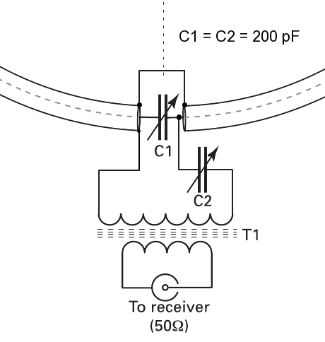
All of these antennas exhibit very low gains on the order of -30 dBi to -36 dBi; therefore, any signal picked up on the feed line degrades the good directional and S/N characteristics of the antenna. A suitable matching transformer can be made to step down the 900 Ohm impedance of an antenna to 50 – or 75 Ohm coax by using two singlewire windings on an Palomar FT-140-43 toroid core. The low-impedance winding for the coax feed line should be 8 turns, and the high-impedance winding for the feedpoint should be 34 turns if 50 Ohm coax feed line is used, or 28 turns if 75 Ohm coax is employed. For minimum direct coupling, space the two windings from each other by placing them on opposite sides of the toroid core.
Another transformer, recommended by Tom Rauch, W8JI, is made of an Ameritron 412-5250 binocular core with a two-turn winding for the feed line and 8’/2 turns for the antenna winding if 50 Ohmcoax is used, or seven turns if 75 Ohm coax is used. Type 73 and type 77 cores may also be used. Because of the low gain of these antennas, you should use a preamplifier ahead of the receiver.
The antenna pattern can be degraded by common-mode currents on the feed line caused by connecting the unbalanced coax to the balanced transformer winding. This can be alleviated by using a choke balun at the transformer end of the cable. The choke is made by winding 10 to 12 turns of the feed line into coil about 12 inches in diameter. Another method is to use enough high-mu ferrite beads at the transformer end of the cable to cover about 12 inches of the coax.
Multi-Element Arrays of the Antenna I used EZNEC to model arrays of the Point-Fed Pennant in two-element end-fire, two-element broadside and four-element end-fire/broadside configurations. In the end-fire configuration, with 135-foot spacing and with the lead element fed 900 lagging, the cardioid pattern is narrower and has a gain of about 3 dB over a single Pennant. The minor lobe at the rear disappears and the null at the rear of the cardioid is much deeper. Figures 4 and 5 show the elevation and azimuth plots for a two-element Pennant end-fire array over good ground.
Figures 6 and 7 show the elevation and azimuth plots for two Point-Fed Pennants in a 315 foot spaced broadside configuration with both elements fed in phase. This configuration provides a gain increase of about 3 dB and a much narrower azimuth pattern compared to that of a single Pennant.
|
|
|
A Diamond form of the antennas described in this article. |
If you have the room, the ultimate receiving antenna might consist of four Pennants in an end-fire/broadside configuration with a 135-foot end-fire spacing and 315-foot pair spacing. The azimuth pattern for this array rivals a 2-k, Beverage antenna. See Figures 6 and 7.
Switchable-Direction Antennas
Two or more antennas can be installed to cover multiple directions. If the antennas are adjacent one another, only one feed line and one impedance-matching transformer are required. However, modeling shows that this cannot be done if the vertical sections of two antennas are adjacent to each other because of the coupling between the closely spaced vertical wires. This means that a Flag antenna cannot be used for this purpose, nor can the Pennant be used if its vertical sections are adjacent to each other. Modeling shows that the Point-Fed Pennant can be used for this purpose when the Pennants are installed pointto-point. The Diamond and Delta can also be used in a switchable-direction array.
The feedpoints of all of the antennas used in a switchable-direction array can be conveniently located closely to one another, so a common nonmetallic support mast can be used where the feedpoints meet. A common feed line can be permanently connected to the lowimpedance winding of the matching transformer, switching the transformer feedpoint winding between elements. Both sides of the feedpoint must be switched to totally isolate the unused antennas) from the active antenna. For a two-direction switchable array, this is easily done using one DPDT relay. As more directions (and elements) are added, the switching circuitry becomes more complex.
Spreading the Word
|
|
|
Figure 6 – Combined elevation plots oi three antennas over good soil. The dashedline is the pattern of two point-fed Pennanis spaced 315 feet in abroadside configuration and fed in phase. The dotted line is thepattern of two point-fed Pennants in the end-fire configuration, spaced315 feet apart and fed with 90ophasing. The solid line is that of a four-element point-fed Pennantarray with 139-foot end-fire spacing and 315-foot broadside spacingwith the lead elements fed -90o out of phase with the in-phase broadside elements. – Tnx N6BV. |
|
|
|
Figure 7 – Combined 30oelevation azimuth plots ot two point-fed Pennants spaced 315 feet apartand fed in phase (dashed line), end-fire Pennants with 135-foot spacingand 90o phasing (dotted line) and the four-elementend-fire/broadside point-fed Pennant array (solid line) over good ground. – Tnx N6BV. |
In August 1998, I described these ground-independent antennas in postings on the Topband reflector. In September 1998, an article titled “Banderas y Gallardetes” (Flags and Pennants) coauthored by Jose Mata, EA3VY, and me appeared in the Spanish edition of CQ Magazine. This generated a great amount of interest in the low-band DXingcommunity and Pennants and Flags began popping up all over the world.
Testing the Pennant
I erected two Point-Fed Pennants at K6SE to see if the antenna behaved as well in the real world as it did in the computer. I installed the Pennants in a point-to-point configuration in directions exactly opposite to each other. A local ham, Will Angenent, K6NDV, volunteered to participate in the tests, so the direction chosen for installation was directly toward (and away from) his location, which is 4.6 miles distant.
In the receiving tests, K6NDV transmitted a carrier and adjusted the power level so that my receiver’s S meter indicated S9 on the Pennant pointing toward him. In the first test, when I switched to the Pennant in the opposite direction, there was absolutely no difference! The same results were obtained on 80 meters.
The Pennants were located near the 160 and 80-meter shunt-fed towers I use for transmitting. Suspecting possibleinteraction, I adjusted the tuning capacitors at the bases of the two towers to detune them and we repeated the tests.
With my towers detuned, the results were very gratifying. On 160 meters, the difference in received signal when switching directions was seven S units; on 80 meters, the difference was six S units! Assuming 6 dB per S unit, this is almost exactly what EZNEC had predicted. The lesson I learned here is that some EWEs may not work because a resonant vertical antenna is nearby.
K6NDV didn’t have a vertical 40-meter transmitting antenna (the Pennant and its relatives respond to vertically polarized signals), so we couldn’t repeat the test on that band. However, we noted a difference of three to seven S units when switching the antennas while listening to sky-wave signals on 7 MHz.
Summary
Soon after the word about these antennas began to spread, e-mail reports from radio amateurs using them began coming in. Here are some of those reports.
Without the Delta receiving antenna, we would not have been able to hear the weak 160-meter signals, especially the Europeans.-F00AAA (Clipperton 2000 DXpedition)
“I use a rotatable Flag mounted on my 160-meter shunt fed tower. It is my primary receiving antenna. 1 use a TR relay at the base of my tower to short out my shunt feed when receiving. ” – K6UR
“EWEs never worked here, so 1 installed two Flags and am pleased with their performance. When comparing my EU Flag with my 585-foot EU Beverage, the Flag is about an S unit down, but the S/N is better. “– K3SX
“We spent three days listening to the rest of the US work ZL9C1 on 160 meters while we couldn’t hear him, so AD6C and 1 hastily put up a Pennant and he was QS copy. Thanks a bunch! “ – N6DX
“I have a Diamond up and it works well on 16040 meters. ” – K5AQ
“I put up a Pennant for the US and a Flag for Africa to compare with my old phased loops. I now copy W7, W5, and WO comfortably on the Pennant and EL2WW is two S points stronger on the Flag than on the phased loops.” – G4VGO
“The Pennant has made a remarkable difference for me on 760 and 80 meters. QSOs with CN8WW and EL2WW on Topband and JA on 80 meters would have been impossible without it. Using the Pennant as my receive antenna has made me not only a convert, but a disciple. ” – VE3UOL
“With 24 dB of preamplification on 160 meters, my broadside Pennants (225 foot spacing) for EU on 160, they are quite comparable to my foursquare, and with a much quieter noise floor. The difference on weak EU 160-meter signals compared to my long EU Beverage is quite small. On 80 meters, the antenna needs only about 12 dB of preamplification and is a real performer, as good as my 80 meters four-square looking into Europe. “ – K1ZM
“On 80 meters. the Europeans are very readable on my roof mounted Pennant here in Buenos Aires. On 40 meters, the antenna is a sweetheart. “ – LU/KY0C
Perhaps you, too, ought to give one of these antenna designs a try!
Notes
1 Floyd Koontz, WA2WVL, “Is this EWE for You?”, QST; Feb 1995, pp 31-33.
2 EZNEC is available from Roy Lewallen, W7EL, PO Box 6658, Beaverton, OR 97007
tel 503646-2885, fax 503-671-9046; w7el@teleport. com.
3 John Devoldere, ON4UN, Antennas and Techniques for Low-Band DXing, (Newington: ARRL, 1994, 2nd ed.)
Earl W. Cunningham, K6SE, was first licensed in 1955 as W8DGP (General class); he obtained his Extra class license in 1963. In 1973, Earl received his BSEE from the University of Houston and was employed by General Electric and Northrop Aircraft Corporation. Earl retired in 1994. It is with great sadness the topband community learned of Earl K6SE becoming SK on 29 April 2007.