by George Wallner, AA7JV
This antenna was developed to meet the need by the TX3A Chesterfield DXpedition for a small, low-band, ground independent directional RX antenna that only requires two support poles. The antenna can provide reasonable performance for the space limited amateur, as it fist into a 60 x 60 foot back-yard. Smaller version will work almost as well.
This design is essentially two half delta loops that are interconnected to create a single antenna, with one transformer and one load resistor. The improvement in RDF over a single flag of similar size is about 2.5 dB.
 The Double Half-Delta Loop RX Antenna
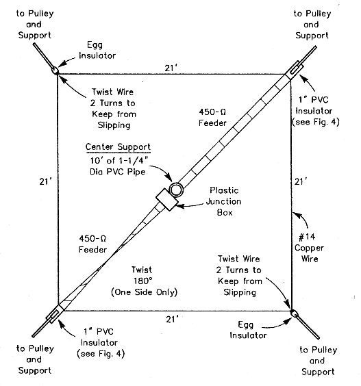
Dimensions: Wire a and d are 7.5 m long with the lower ends at 1.5 m above ground. The two vertical wires (wires a and d) are 22 meters apart. Note that wires b – e and f – c form single wires, which are bent at the half-way point between the vertical wires and held at 1.5 meters above ground by a short support post. Wires b – e and f – c cross each other but are not connected to each other (see detail). Wire diameter is not critical and the antenna will work equally well with bare or insulated wire. The antenna will pick-up less noise when placed higher than shown above.
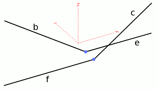
Detail showing wires 2-3 and 4-5 crossing each other
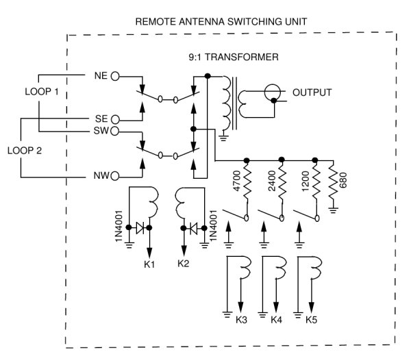
The feed point uses a wide band 12:1 transformer to match the loop to a 75 ohms coax, or a 16:1 transformer for 50 ohms. The loading resistor, set for best RDF, is 1200 ohms. (Better front-to-back can be obtained with a 950 ohm resistor – the actual value depends on ground conductivity.)
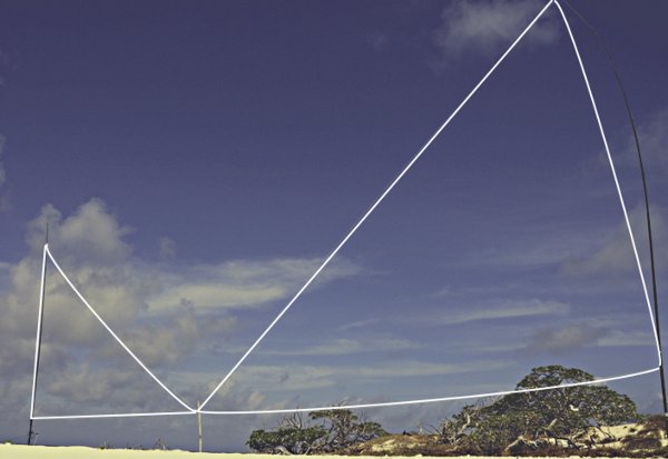
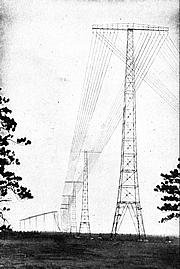
The DHDL Antenna in real world
Note that there is nothing special about the dimensions of this antenna. The more area the wires enclose, the larger the signals (higher gain), but the RDF may get slightly worse. Also, the larger antenna will not work on the higher bands. (The upper cut-off is approximately where the total wire length reaches ¼ wavelength.) Smaller dimensions will produce small signals and may need a pre- amplifier. Note, however, that below a certain size, the antenna’s own thermal noise will exceed the signal it produces and the antenna will become useless. (Unfortunately you can not build a miniature version and use it with a 40 dB amplifier.)
EZNEC indicates the following performance:
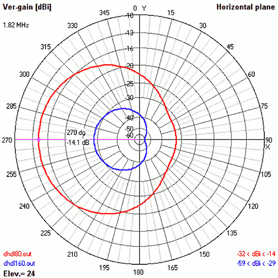
Horizontal pattern
(160m – blue, 80m – red)
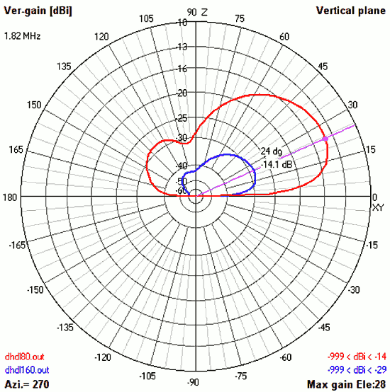
Vertical pattern
(160m – blue, 80m – red)
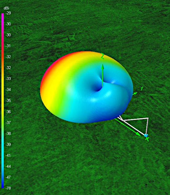
3-dimensional pattern
(160m)
Because this is a low gain antenna, care should be taken to prevent noise carried on the outside of the feed-line coax being picked up the loop wires. Use #31 ferrite cores with several turns of the coax to form chokes on the coax feed-line. Grounding the shield of the coax between the chokes can also help. Keep the antenna away from noise sources, resonant verticals (min ¼ wavelength) and large metal objects, such as tin roofs.
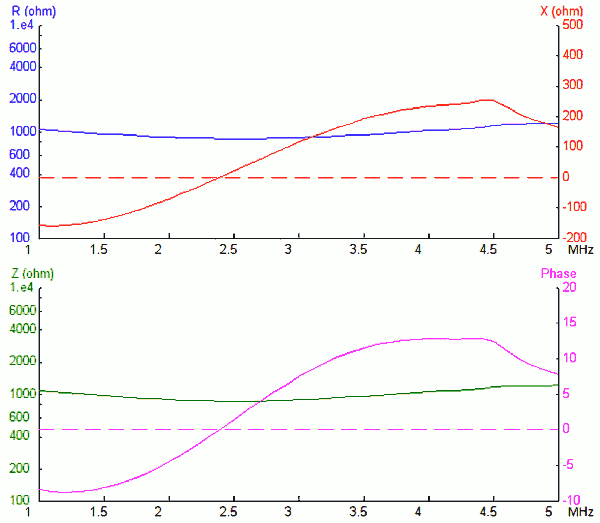
Impedance vs. frequency

A Smith chart of the DHDL Antenna
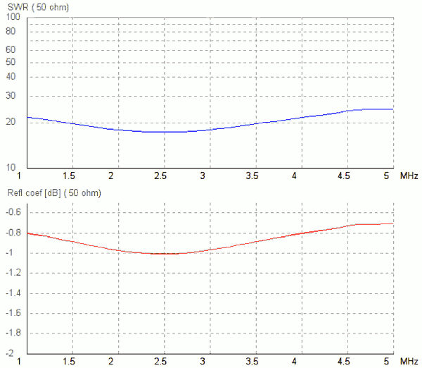
SWR Chart
Conclusions: This antenna ain’t no Beverage. But, it is better than a single flag or EWE, and almost as good as two phased EWE-s in the same space.
(Analysis in 4nec2, my own drawings)
Download the AA7JV description here.