The TinyKeyer
the (possibly) World’s Smallest Fully-Featured CW Keyer with Computer Support
Introduction
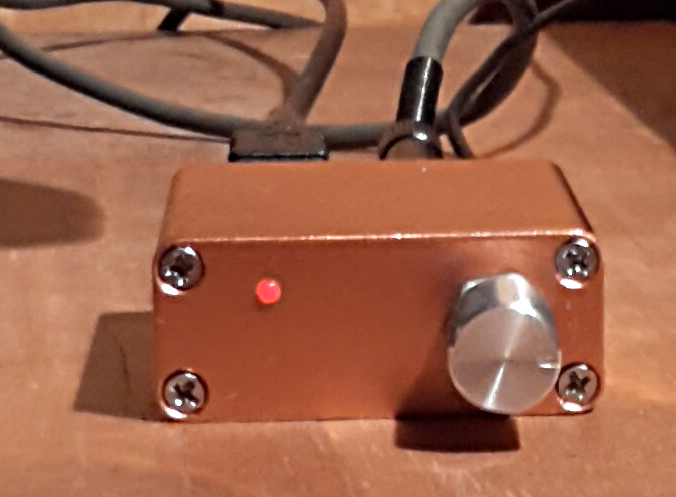
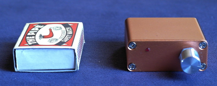 This keyer, based on Arduino design, employs the famous K3NG code. It can be used with any Windows/Linux/Mac logging or contesting software with Winkeyer USB (K1EL) support. The credit & big kudos goes to Anthony Good (Goody), K3NG, who did the tremendous work. It is a very small unit (outer dimensions 45 x 45 x 18.6 mm, appx. 1.8 x 1.8 x 0.73 in) which does not have any fancy options (a zillion of buttons, psychedelic flashing LED lights or cockatoo colored displays). It is intended for regular CW work and contesting with computer support, most of functions should be adjusted and operated via the computer. For standalone work an acoustic menu in command mode is used. Otherwise, only speed control knob and a mini LED indicating the command mode is on the front panel, nothing more.
 This construction is not intended for beginners, an intermediate-level builder’s experience (also with SMD parts) is needed. Although this circuitry is quite simple, it does not mean that everybody who already built a traditional kit with leaded parts must be successful. You need basic tools for SMD parts, a clean and accurate work is mandatory. Otherwise you will be surprised how uncomplicated it is to build. All of the circuitry is contained on a single board, while the Arduino Nano Rev. 3 module is sandwiched to the main board. Wiring is minimal, unlike some tricky mounted parts (rotary encoder, input and output receptacles) may require some kind of preparation. A professionally made, double sided L shaped PC board with solder mask, metal plated through-holes (vias) and silkscreen printing is used (Gerber data available).
Although the Arduino Nano is listed as retired, this board is still available in good quantities, at least on eBay. Don’t buy the Arduino Nano Rev. 2.3 with ATmega168 Microcontroller! It has a half of Flash Memory, SRAM and EEPROM and can’t accommodate the program!
Specifications:
- CW speed adjustable from 1 to 999 WPM
- Programming and interfacing via USB port
- Rotary Encoder Speed Control
- Command mode for using the paddle to change settings
- Logging and Contest Program Interfacing via K1EL Winkey 1.0 and 2.0 interface protocol emulation
- Optional PTT output with configurable lead, tail, and hang times
- Iambic A and B modes
- CMOS Super Keyer Iambic B Timing
- Ultimatic mode
- Bug mode
- Straight key support
- Paddle reversal
- Farnsworth Timing
- Adjustable frequency side tone
- Keying Compensation
- Dah to Dit Ratio adjustment
- Weighting adjustment
- “Dead Operator Watchdog”
- Autospace
- Wordspace Adjustment
- Non-volatile storage of most settings
- Sleep Mode
- QLF (“Messy” Straight Key Emulation)
The Design
The main goal – simple, cheap and very straightforward construction.
Many keyers have usually some (possibly a lot) of unnecessary options which are never used. Memory buttons, knobs, LEDs, multiple outputs (sometimes opticallyisolated) – the mechanical construction is complex, high requirements on box cutting and drilling, the result is an “amateurish” look with hand tools spurs etc. A keyer intended to operate with a computer is different from a Swiss Army knife for standalone operation. Within many years of a Winkey USB use I discovered that I never used a memory button, even the Speed Control knob is collecting dust, the whole keyer control is done from the computer keyboard.
There is a very popular but false idea that a keyer needs an opticallyisolated output. Actually a majority (if not all) of modern transceivers keying a very low voltage with very low current by switching the key(er) input to ground. There is more important to have a low resistance output than an isolated ground. Also, in complex (messy) station wiring all grounds are finally connected together, sometimes with very poor RF properties (high impedance) etc. A common mode choke (few turns on a ferrite toroid – I prefer the Fair Rite 31 mix) is often the only efficient medication. So, a simple FET switch with low RDS(ON) offers much better results than an optoisolated output.
Also, a number of bright blinking LEDs is rather annoying than useful.
Schematic

Parts List
|
ID |
Package |
Quantity |
Value/Type |
Note |
|
C1 |
Elko SMD B size |
1 |
10u/16V |
Tantalum 1206 |
|
C2, C3, C4, C5 |
C 1206 |
4 |
1n/50V |
|
|
D1 |
LED 2 mm dia |
1 |
L-1034ID Kingbright |
|
|
J1, J2 |
Jack stereo 3.5 mm |
2 |
PJ-392 |
1) |
|
JP1 |
Pin Header Straight 1×02 |
1 |
ASR ON/OFF |
2) |
|
Q1, Q2 |
SOT-23 |
2 |
BSS138 |
or 2N7002 |
|
R1, R2, R3, R4, R6 |
R 1206 |
5 |
10k |
|
|
R5 |
R 1206 |
1 |
560 |
|
|
R7 |
R 1206 |
1 |
1k |
|
|
R8, R9 |
R 1206 |
2 |
390 |
|
|
S1 |
Rotary encoder |
1 |
ALPS STEC12E07 |
many equivalents 4) |
|
SW1 |
1 |
push switch |
part of S1 |
|
|
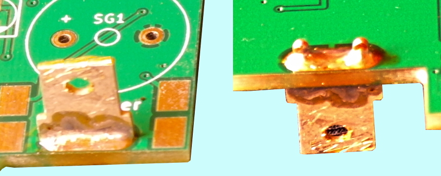
SG1 |
Buzzer 14×7 RM7.6 |
1 |
KPEG-166 |
many equivalents |
|
U1 |
arduino nano |
1 |
||
|
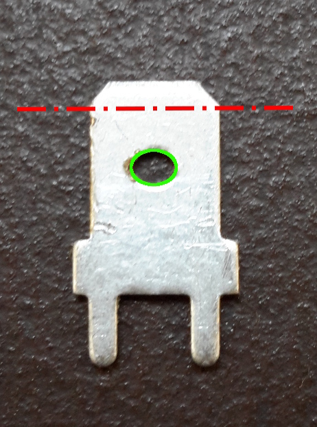
FASTON 6.3 x 0.8mm |
1 |
PCB mount, RM 5 mm |
tin plated |
|
|
ALU Box |
1 |
45*45*18.56 mm |
3) |
|
|
PCB |
1 |
Notes:
- bought on eBay from China
- pins (square profile) soldered directly to the PC Board. No plastic ‘basement’ to save height.
- bought on eBay from China at Chip Partner store. Look for the Article #401088049930 or description containing a string “45*45*18.56m” or SKU:7497.
- there are many equivalents like Alps EC11E09244BS, Sunrom 4310, etc. Almost any type of the same size and pinout can be used.
|
The PJ-392 receptacles are low quality parts. A jack goes very tight to this receptacle. Do not apply force to insert the jack, both can be damaged! A PJ-392 receptacle must be “trained” before use by multiple inserting a shaft of 3.4 – 3.5 mm (1/8″) diameter. |
| TIP: Avoid cheap, poor quality jacks! If the tip can be rotated, throw it away! The body of input and output 3.5 mm (1/8″) jacks can’t be too thick, a large diameter of some types may cause problems! I am using these thin (6.6 mm dia), high quality gold plated full-metal ones. | 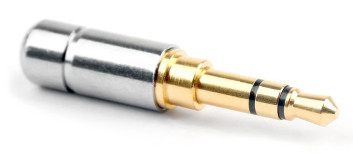 |
Parts preparation
Arduino
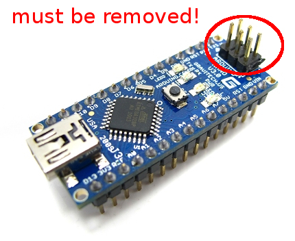
-
remove the ISP header from the board. If your Arduino comes in the kit form, don’t install the ISP header!
-
load the code into your Arduino first, before any soldering. An early programming procedure is the only test of your Arduino board, presuming that if a board can be programmed, it is good. Keep in your mind that the Arduino is permanently attached to the PCB (ie. NOT removable!) and a replacement is very difficult.
The Arduino Nano Rev. 3 board is available in two versions, at least on eBay. The original Nano which is initially a product of US company Gravitech is equipped with FT232RL FTDI chip USB connection to the computer.The Gravitech boards have outstanding compatibility with all operating systems but the boards made in 2009-2010 years may have a significant issue – the FTDI chip has ungrounded pin 26 which turns the FT232 into Test Mode. Such board is not visible as USB device, can’t be programmed via USB and can’t be operated in usual way. It can be fixed by a simple solder bridge between pins 25 and 26 on the FT232RL, See here.
The Chinese clone employs the CH340 chip which is significantly cheaper, these Arduinos can be bought under $2 on eBay. They appear to be newer, in contrary to many of the Arduino community I must say that there are no compatibility issues – tested with the Ubuntu 16.04 64bit Linux, Wine 1.6.2 Standard Suite in Linux (and also Wine 1.9.6 Standard Suite) and Windows XP Pro Service Pack 3. In other words, the CH340 chip works like a champ, no need to solder in a very tight space so don’t hesitate to buy these cheap Arduino clones.
Linux users can check the Arduino presence with this script, I named it devcheck.sh.
#!/bin/bash

for sysdevpath in $(find /sys/bus/usb/devices/usb*/ -name dev); do
    (
        syspath="${sysdevpath%/dev}"
        devname="$(udevadm info -q name -p $syspath)"
        [[ "$devname" == "bus/"* ]] && continue
        eval "$(udevadm info -q property --export -p $syspath)"
        [[ -z "$ID_SERIAL" ]] && continue
        echo "/dev/$devname - $ID_SERIAL"
    )
done
The devcheck.sh response to different Arduino types on USB1.
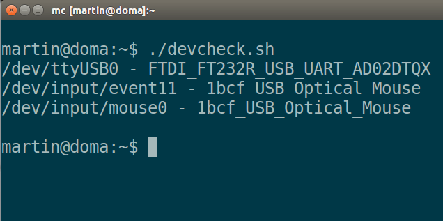
devcheck without any additional device. |
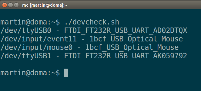
devcheck with TinyKeyer equipped |
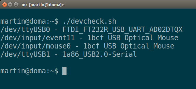
devcheck with TinyKeyer equipped with CH340 on USB1. |
|
In Linux, the Chinese CH340 is detected and directly supported without any problem. Some other Linux distributions (as well as the ‘geek’ distributions which are very basic) may come without CH340 support. A new kernel must be created, the CH340 must be compiled directly into the kernel, not as module! In Windows, the Plug & Play system detects a new device which must be enabled with an appropriate driver. FTDI drivers mostly work, for the Chinese CH340 chip the proper working driver is here. Anyway, don’t try to program the Arduino if the board is not recognized by the system!
Programming
You will need the Arduino Software (IDE) available for free at [2]. There are versions for Windows, Mac OSX 10.7. Lion or later, Linux 32 bit, Linux 64 bit and Linux ARM (experimental). All work was done in the experimental Arduino 1.6.12. Hourly Build 2016/09/08 11:33, version Linux 64 bit. The regular releases may show some issues (possibly library location?) but the hourly build WORKS as well as the old version 1.0.6. So, don’t be surprised, don’t ask me, please, try first the actual hourly build, the second option is the old version.
|
While programming (loading the code) the jumper JP1 (ASR) must be removed, otherwise (operating) must be JP1 inserted! |
The initial code [3] was slightly modified. A new set of headers (keyer_features_and_options_tinykeyer.h, keyer_pin_settings_tinykeyer.h and keyer_settings_tinykeyer.h) was created to avoid confusion with other code derivatives, new headers must be also defined in the main code file k3ng_keyer.ino.
The initial setup is to determine the proper port (actual Arduino connection) and board type. Choose Arduino Nano, the processor type must be ATmega328. If the IDE shows processor type ATmega168 without any other option, your board is probably not the Rev. 3 but an older one which can’t be used! All should be done in the Tools menu item.
Get the code here. When the Arduino Software (IDE) starts for first time it tends to create a folder named sketchbook. Use this folder, unzip the downloaded file into this folder. A subfolder named k3ng_keyer should be created. Start the Arduino Software (IDE), navigate to the newly created subfolder and open the project.
Rotary encoder
A rotary encoder is much better choice than a potentiometer. It is much smaller, cheaper and more reliable. The TinyKeyer utilizes a multi-step rotary encoder with a nice ‘clicking’ feel. The encoder is different from a potentiometer in that an encoder has full rotation without limits. The unit outputs gray code so that you can tell how much and in which direction the encoder has been turned.It has a pretty handy select switch (by pushing in on the knob) used to switch the keyer into command mode.
There are many different types in the same size. An encoder with short plastic shaft can be also used. Cut the shaft before installation to match your knob! The installation of the rotary encoder is a bit tricky using a FASTON blade contact as support.
Let’s build!
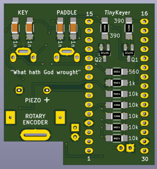
Start on the bottom side of the PCB. First, install all SMD parts:
 |
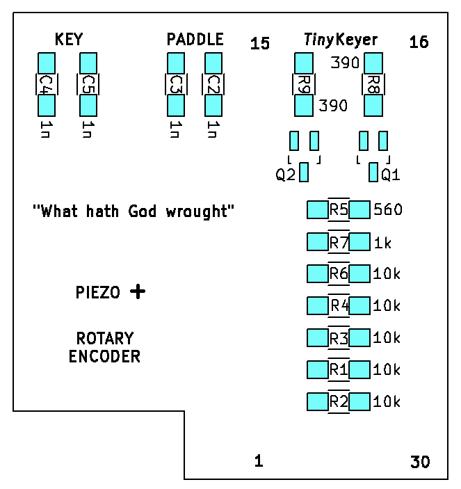 |
-
install C2, C3, C4 and C5 (blocking capacitors 0.001 μF, SMD 1206)
-
install R1, R2, R3, R4 and R6 (resistors 10 kohm, SMD 1206)
-
install R7 (resistor 1 kohm, SMD 1206)
-
install R5 (resistor 560 ohm, SMD 1206)
-
install R8 and R9 (resistors 390 ohm, SMD 1206)
-
install Q1 and Q2 (switching FET BSS138 or 2N7002, SOT-23)
(soldering pads = blue)
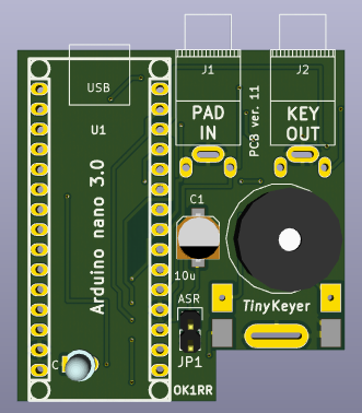
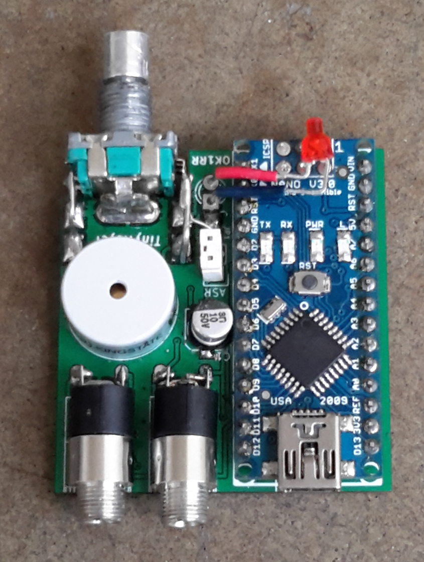
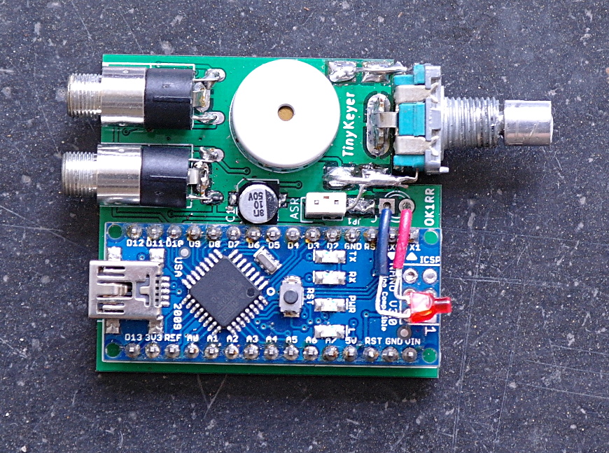
Continue on the PCB top side:
 |
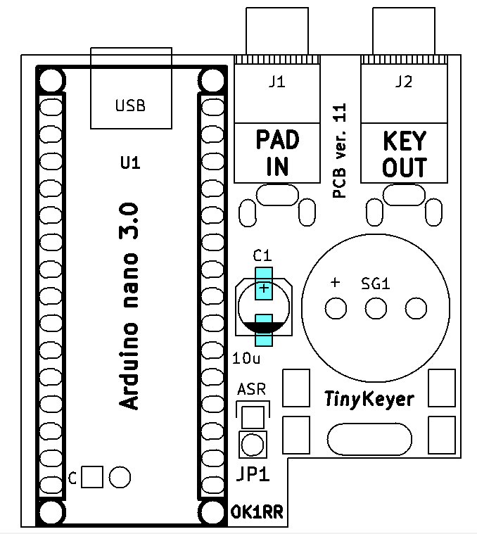 |
-
install the C1 (10 μF, tantalum (SMD 1206) or alu (SMD B size) electrolytic capacitor).
-
install the rotary encoder (is the shaft length OK?). This is a bit tricky:
|
 |
|
 |
|
|
|
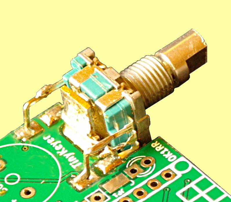 |
The encoder connection should be better visible here:
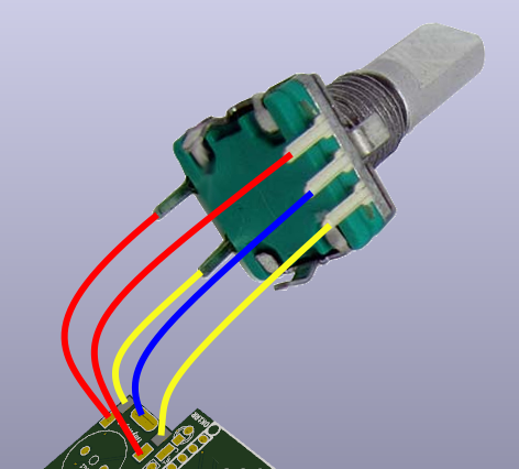
The red wires from upper pins must be wired. It is not bad idea to use the stiff square-profiled pins. The yellow wires mean encoder pins directly soldered to the PCB. The blue wire (GND) goes directly to the FASTON blade which is grounded.
And continue…
- install the jumper pins. Insert two square profiled blank pins into jumper body and put this ‘assembly’ to the PCB. The jumper body must touch the PCB. Temporary solder the pins to the PCB with very low amount of solder, remove the jumper body and check the pin length. If OK, return the jumper body and solder the pins to the PCB.
- install the PJ-392 input and output 3.5 mm jack receptacles. The middle GND pin goes directly to the PCB, the tip and ring contacts must be lengthened with small cuts of wire (stiff square-profiled pins can be used). The pins/wires must be shaped before soldering to ensure proper receptacle position.
- install the piezo buzzer SG1 (KPEG-166 or similar, RM7.6)
- install the Arduino board. The headers are soldered directly to the PCB, the board is not removable.
- install (as last part) the LED. The leads must be shaped to allow the flat top of the LED to protrude through the hole in the front panel. The good position is a the Arduino board level (the LED touches the board) and at least in the middle on the Arduino board width. The symmetry with the encoder knob is also a good idea.
Now, your TinyKeyer should be operational. Connect the Arduino USB connector (mini USB) to an USB port of your computer. A HI should sound. Connect the paddle and test your keyer. Prepare also the keying cable to your radio.
Don’t miss some images…
|
While programming (loading the code) the jumper JP1 (ASR) must be removed, otherwise (operating) must be JP1 inserted! |
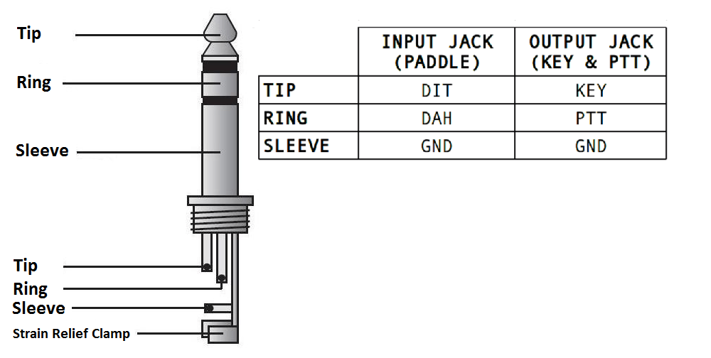
Input (paddle) and output (keying & PTT) 3.5 mm (1/8″) jacks wiring.
Now the command mode menu should be tested:
TinyKeyer commands (as of 2021 Jan. 26, firmware version 2021.01.25.01)
A – Switch to Iambic A Mode
B – Switch to Iambic B Mode
C – Switch to Single Paddle Mode
D – Switch to Ultimatic Mode
E – Announce the speed in WPM
F – Adjust sidetone frequency* (“acoustic menu”)
G – Switch to bug mode
H – Set weighting and dah to dit ratio to defaults
I – TX enable / disable
J – Dah to dit ratio adjust* (“acoustic menu”)
K – Toggle Dit and Dah Buffers on and off***
L – Adjust weighting* (“acoustic menu”)
M – Change command mode speed
N – Toggle paddle reverse
O – Toggle sidetone on / off
P#(#) – Program a memory
Q – Adjust keying compensation (left paddle = increase, right paddle = decrease)
R#### – Set serial number to ####
S – Alphabet code practice
T – Tune mode
U – Receive / Send Echo Practice
V – Toggle potentiometer active / inactive
W – Change speed* (“acoustic menu”)
X – Exit command mode (you can also press the command button to exit)
Z – Autospace On/Off
? – Status**
Remarks:
* Left paddle decreases, right paddle increases, squeeze exits.
** Status is played in Morse in following order:
1. Speed in WPM
2. Keyer Mode (A = Iambic A, B = Iambic B, G = Bug, S = Single Paddle, U = Ultimatic)
3. Weighting (default = 50)
4. Dah to Dit Ratio (default = 3)
*** Reported with ON and OFF in Morse Code. Active in Ultimatic mode only, in other modes sounds ERR.
**** Feature (FEATURE_ALPHABET_SEND_PRACTICE) must be set to ON in keyer_features_and_options_tinykeyer.h in before Arduino programming
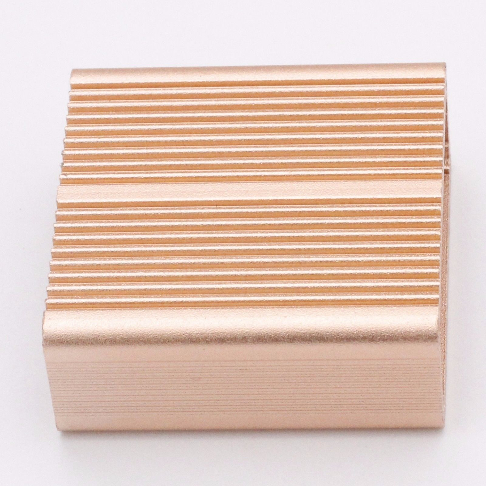
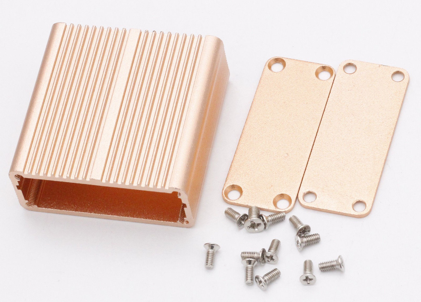
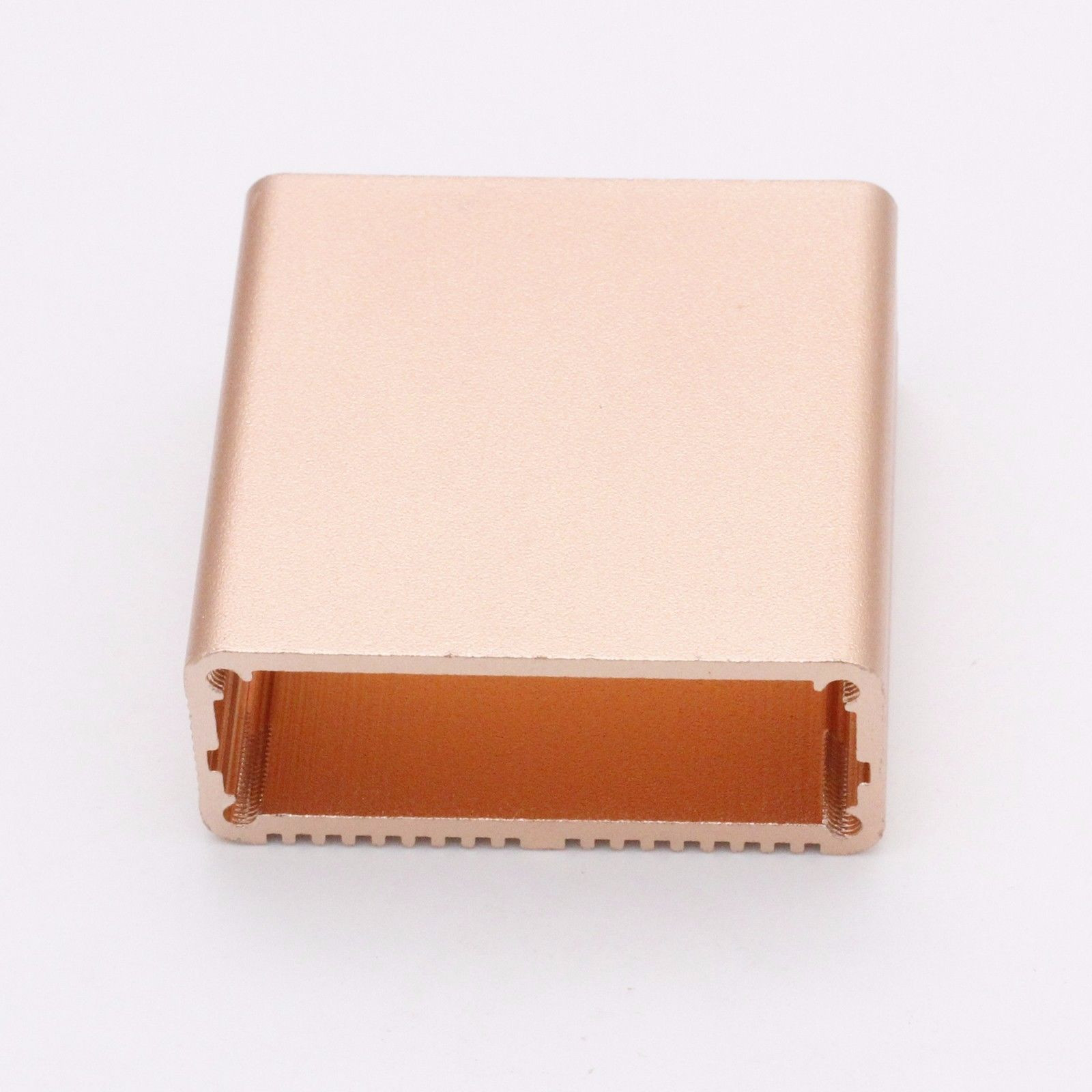
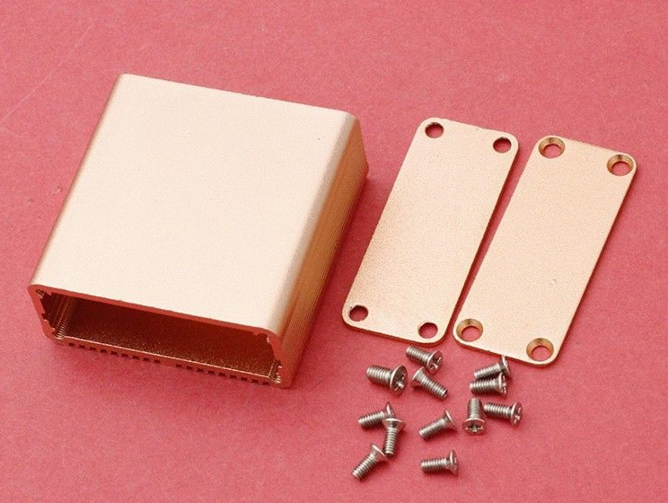
Housing
The keyer is housed in a miniature diecast enclosure available on eBay.
 |
 |
 |
 |
This minibox is so nice that it initiated the project! The drawing below shows how the PCB sits in the box. The slot intended for the PCB is not used (!), the PCB sits on the protrusion just above the threaded hole. Only such arrangement ensures that we will be able to place the whole electronics into this minibox. It is also possible to turn the box with its ribbing up for those, who wants.
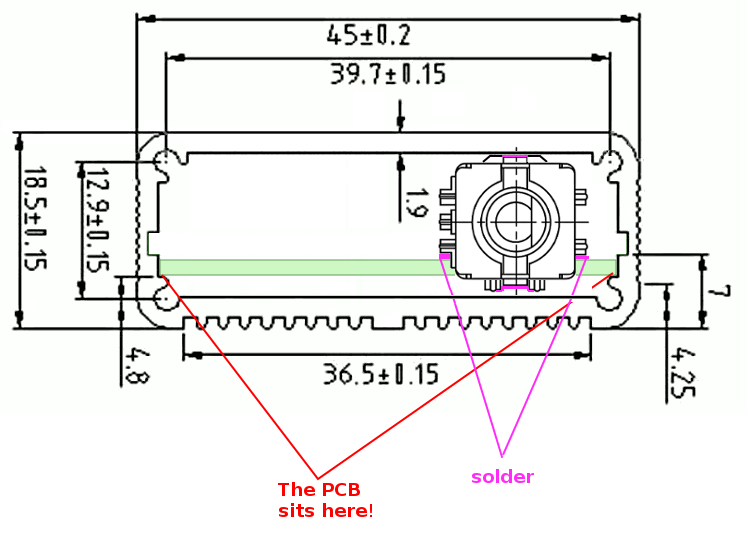
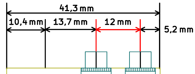
The only work needed is to drill front and bottom panels (units – millimetres). The corner holes are factory made.
Downloads
All TinyKeyer related files (this guide in PDF format, a Command Mode quick reference, a recent firmware version, Gerber files for PCB fabrication, PNG sketches of both panels and the devcheck.sh script mentioned above) located on a dedicated page here.
Notes
[1] Arduino, Compare board specs https://www.arduino.cc/en/Products/Compare
[2] The open-source Arduino Software (IDE) https://www.arduino.cc/en/Main/Software
[3] K3NG Arduino CW Keyer https://github.com/k3ng/k3ng_cw_keyer