by Floyd Koontz, WA2WVL
first published in QST (ARRL), February 1995
A New Design
One fundamental of directive wire-antenna design is that two or more parallel wires carrying similar RF currents produce directivity regardless of the phase or amplitude of the currents, if the wires are separated significantly (greater than 0.05 l). I surmised that if a short wire (less than 1/4 l) were formed as an upside-down U and fed against ground, good F/B directivity would result.
Using Brian (K6STI) Beezley’s AO software, I modeled such an antenna (with a terminating resistor to ground at the far end of the wire). Success was immediate, with F/B ratios greater than 30 dB predicted. Since AO assumes that the ground beneath the antenna is perfectly conducting, the initial result was suspect.
I loaded the AO dimensions into K6STI’s NEC-WIRES software, which takes into account the ground conductivity and dielectric constant beneath the antenna. Compared to AO’s output, the results dove into the 15 to 20-dB region, but the F/B was real. With some readjustment of the antenna dimensions and the value of the far-end resistor, the F/B increased to more than 30 dB. that from a piece of wire between two ground stakes! What could be simpler?
A Beverage It Ain’t
This antenna (Figure 1) looks amazingly like a Beverage, but its method of operation is entirely different. By analyzing the RUN file in AO, you can see that for optimized height and length, a phase shift of about 45o occurs between the center of wire 1 and the center of wire 3.
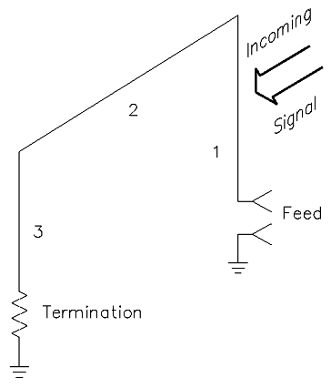
Figure 1. The Ewe is the receiving antenna. The antenna end attached to the resistor is the rear.
The antenna produces a cardioid pattern.

Figure 2A. Azimuth pattern of a single Ewe over average ground.
Taking into account the 180o phase shift caused by the direction of the currents in wires 1 and 3, the total phase shift is about 135o, with wire 3 leading (a reflector). From this, you can see that the Ewe receiving antenna is essentially a two-element driven array in which the rear element (wire 3) is fed via the top wire (wire 2). Wire 3 has about 65% as much current as wire 1. Figure 2 shows the azimuth and elevation patterns of a single 80-meter Ewe over average ground.
Because part of the antenna is horizontal, I was concerned about noise pickup degrading the overall results. The horizontal gain computed to be about 20 dB lower than the vertical gain, and at a high angle off the side.
One surprise is that the F/B holds over several megahertz. That led me to design a second antenna covering 1.8 to 4.0 MHz. The calculated F/B is greater than 25 dB over this entire range without adjustment. This design will be shown later.
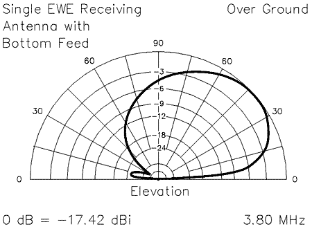
Figure 2B. Elevation pattern of a single Ewe over average ground.
Feeding and Terminating the Ewe
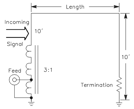
Figure 3. A 10-foot-high bottom-fed EWE with
a 3:1 impedance-matching transformer and a resistive termination.
Figures 3 and 4 show two ways of feeding the EWE. The basic feed impedance is about 450 ohms, so a transformer with a turns ratio of 3:1 provides a good match. The value of the terminating resistor varies according to the wire height, wire length and band of operation, and whether bottom feed or top feed is used. I devised the top-feed system so that the RG-58A coax could be run overhead. Because I considered a wire 10 feet high something that could be managed easily by most amateurs, I used NEC-WIRES to generate Tables 1 through 4 using a 10-foot height as one parameter.
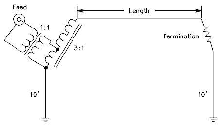
Figure 4. A top-fed, 10-foot-high EWE with
a 3:1 impedance-matching transformer and a resistive termination.
|
Table 1 – Ewe Parameters for Bottom Feed at 3.8 MHz,with an Antenna Height of 10 Feet and Elevation Angle of 30o
|
|
Table 2 – Ewe Parameters for Bottom Feed at 1.8 MHz,with an Antenna Height of 10 Feet and Elevation Angle of 30o
|
|
Table 3 – Ewe Parameters for Top Feed at 3.8 MHz,
|
|
Table 4 – Ewe Parameters for Top Feed at 1.8 MHz,
|
Reversible Ewe for 80 Meters
In order to experiment with this antenna, the first one built had identical 3:1 turns ratio ferrite transformers (50 to 450 W) at both ends of the EWE. Two RG-58A coax cables ran to the shack so that the feed and the termination were at the receiver. This allowed nulling real signals and noise arriving by skywave to determine the antenna’s effectiveness. I quickly discovered that a high F/B could not be obtained with a purely resistive termination, so my old Beverage control box was pressed into service. This control box has an adjustable RLC termination, which was just what I needed. Results on nulling skywave signals ranged from minimal to as high as 40 dB. This is as expected, since only stations directly off the back are in the pattern null. The termination consists of a 500-pF air-dielectric variable capacitor, a 4.7-µH inductor (a low-Q inductor is adequate), and a 100 W potentiometer, all in series.
160 and 80-Meter Design
As mentioned before, a compromise design was made to cover 1.8 to 4 MHz. The optimum dimensions are shown in Figure 5. Gain at 1.8 MHz calculated as -22 dBi and at 4 MHz, -12.3 dBi.
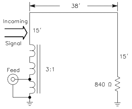
Figure 5. An 160/80-meter EWE 15 feet high.
Two-In-Line Array

Figure 6. An array of two 10-foot-high EWEs.
Next, I investigated an array of two Ewe antennas. When two elements are fed as an endfire array, the forward beamwidth remains the same, but the pattern off the back improves. Figure 6 shows the in-line physical configuration that gives excellent results on 80 meters. Feeding both antennas with equal currents and 135o phasing provides the patterns shown in Figures 7A and 7B.
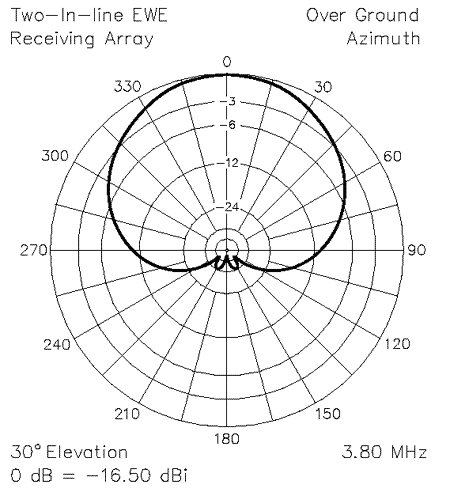
Figure 7A. Azimuth pattern of the dual-EWE array of Figure 6.
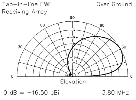
Figure 7B. Elevation pattern of the dual-EWE array of Figure 6.
Two-in-Broadside Array

Figure 8. A pair of side-by-side Ewes fed in phase to produce
a narrower azimuth pattern (see Figure 9).
Two EWE elements, side by side, can be fed in phase to produce a beam that is much narrower in azimuth. Element spacing should not exceed 5/8 l (about 162 feet at 3.8 MHz). Figure 8 shows the physical configuration used, and Figure 9 shows how the pattern varies with element separation. Use equal-length feed lines run to a common central point, beyond which the lines can be placed in parallel.
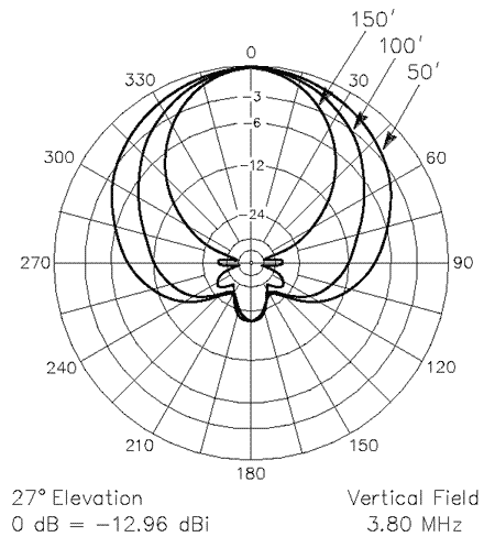
Figure 9. Azimuth patterns of the Figure 8 array for varying
degrees of antenna separation.
Construction
Little needs to be said about how to build this antenna. Height and length are not critical and small ropes or cords can be used to pull up the top wire. I stretched my experimental antenna from the corner of my house to a convenient wooden pole. Of course, trees or towers will do fine as supports. I recommend that the upright wires be not closer than 10 feet to a tall metal tower and that the antenna not receive in the direction of a supporting tower.
For the ground rods, I used 2-foot, 8-inch pieces of copper-plated steel, made by cutting 8-foot ground rods into three pieces, but common pipe will work. The small ferrite transformer and the potentiometer are mounted in small diecast boxes equipped with binding posts on the top. The boxes are clamped to the ground rods using stainless-steel hose clamps. Any type of copper wire can be used for the antenna.
I use a pair of 11-dB low-noise amplifiers to bring signal levels up to levels comparable to those provided by full-size antennas.
Summary
Antennas much simpler than this. that play as well as this. are hard to come by. Give a EWE a try. I’m sure you’ll find it improves ewer receiving capability on the low bands!
(1) Floyd Koontz, WA2WVL, “A High-Directivity Receiving Antenna for 3.8 MHz,” QST, Aug 1993, pp 31-34.