a reprint of the revolutionary article by Thomas H. Schiller, N6BT (QST July, 2000)
One of the most important aspects of building and evaluating antennas is actually using them in environments where the performance can be measured in a meaningful manner. Claims for how well various antennas “work” are as plentiful as snow flakes in winter and this subject has surfaced in one way or other at every forum or club discussion I have presented since 1978. How many times have we heard someone say, “My antenna really ‘works’”?
Performance Envelope
What does the word, “work” mean? The answer is, everything does work, to one degree or another. I hope that everyone will agree that this statement is absolutely true. How well it “works” is the issue and this is the “performance envelope” of the antenna system. The first time I presented this idea was at the ARRL Pacific Division Convention in the fall of 1998. It was well received and I was encouraged to completely rewrite all of my material. My revised presentation was first viewed at the ARRL Southwestern Division Convention in the fall of 1999. It was further augmented and presented a couple weeks later to a packed double room audience at the ARRL Pacific Division Convention. There were more than a few eyebrows raised when I began with the digital slide, “Everything Works.” It seemed to be out of character, because I always focus on efficiency.
I followed with an example of my first antenna, which enabled me to make contacts all over the West Coast on the 40-meter Novice band. I was WV6KUQ and the year was 1959. It was a very simple antenna, since it was the screen on my bedroom window. I made contacts, so I thought it was doing all right. My high school science teacher, the late “Doc” Gmelin, W6ZRJ, tactfully informed me that it probably was not the best antenna and that it could be improved. He was the one who had given me my Novice test, became my Elmer and later was my high school physics teacher. At his suggestion, and with my Dad’s assistance (both he and my Mom always encouraged and supported my adventures), we put up a Windom antenna. It was easy and did not require coax. The Windom certainly was not the greatest, but it was a tremendous improvement over the window screen. The performance envelope of the antenna system had been extended.
Witnessing the obvious improvement between the window screen and the Windom sparked my long-term interest in antennas. The performance difference between the twocould best be summarized as, “Wow! This is going to be a lot more fun.” The Windom antenna enabled me to make my first out-of-state QSO with a fellow Novice back in Delevan, Wisconsin. This was almost 2,000 miles away and we talked for more than 30 minutes. We then put up a vertical antenna for 40 meters made by attaching a large, insulated stranded wire on a wooden 2 × 4 frame. The ground system was a single ground rod (not very efficient, I later learned). This antenna enabled me to make my first DX QSO with JA2CMD. With my Dad’s help again, we graduated to a 2-element, trapped tribander, which we managed to raise to 30 feet on a telescoping mast atop the roof. From my experience it was so impressive that I thought it must be the absolute best antenna possible.
This impression, of course, was incorrect. It was only the best one I had used so far. It was my personal, limited perception; certainly not an accurate assessment of the true situation. Strange as it might seem, it has taken years to realize that most everyone goes through this same learning process. Today, even with all the books on various antenna subjects, there remains a similar gap between perception and reality. My reality came into sharp focus in 1983.
Gary Caldwell, VA7RR (WA6VEF at the time), and I went to Saipan for the CQWW CW contest (AH0C). I had operated twice before from the southern end of the island utilizing the existing quad antennas of Byrd Brunemeier and Don Bower who worked for Far East Broadcasting Company (FEBC). After setting up the stations, we were asked if we would rather move to the north end of the island and use the FEBC short-wave broadcast antennas. These were located on Marpi Cliff, about 400 feet above the ocean. That decision took about two seconds.
 We had brought along a typical trapped (new) tribander and a 30-foot mast. We also had about 1200 feet of coax. The antennas made available for us at FEBC’s site were three TCI-611 curtains, designed for operation between 8-18 MHz (we used them on 40, 20, 15 and 10 meters). Each one cost about $300,000 (in 1982 dollars) and consisted of a pair of 240-foot towers with 61 phased dipoles between them. There was a passive reflector behind all the dipoles and a switching system to move the main lobe from side-to-side. These are huge antenna systems! We set up the stations in the main operations building and the slew controls were behind us on a large panel. These curtain antennas were specified to provide 21 dBi gain and a F/B ratio of 20 dB. The tribander was specified to provide about 8.5 dBd, or 10.6 dBi. It was a fascinating observation that to achieve an additional (theor etical) 10 dB over the trapped tribander required so much more hardware (and money).
(30 to 180 feet) on a 190-foot
rotating tower at N7ML.
A triangular, phased kW Illuminator “array.”
A triangular, phased kW Illuminator “array.”
Part of the signal level difference can be attributed to the location and the take-off angle of the cliff. Our 100 W to the tribander was the same as the kilowatt on Guam, so the cliff location made up the power difference, or about 10 dB; however, both our tribander and the curtain were looking over the same cliff. To try to satisfy everyone on this comparison, let us make an impossible assumption that the difference between the curtain and our tribander locations (in reference to the same cliff) accounts for 30 dB. The remaining difference is still 20 dB and must be attributed to the performance envelopes of the tribander and the curtain.
The true difference between the antennas was so far removed from the specifications that something did not make sense. Our performance envelope had been recalibrated to a limit that can be achieved only by a handful of antenna systems used in Amateur Radio. The challenge to understand the observed difference in performance envelopes led me to design, build, and evaluate hundreds of antennas. These efforts answered the questions about performance and also became the genesis and core of an antenna design philosophy, which has since been produced and marketed under the name “Force 12.”
The Illuminator Project
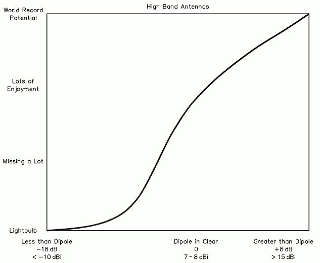
The performance envelope addresses the practical relationship between enjoyment of Amateur Radio and antenna performance. The entire station should be considered. However, the radios available today are all pretty good, so the antenna system is the major key. The primary effort in “The Illuminator” project was to quantify antennas (performance in dBi) and relate this to true performance. The basic chart relating performance to enjoyment is shown in Figure 1. It was developed with the assistance of many knowledgeable people, including typical amateurs, DXers, contesters and manufacturers.
The chart is intended to indicate the relationship between generalized antennas and expected enjoyment of Amateur Radio. It is certainly not a comprehensive representation of all antenna types and what can be accomplished. The ranges across the bottom of the chart, however, are pretty good indicators of antennas amateurs have used. The chart does not indicate take-off angle, which is very important for working DX, but not everyone is interested in working long distances. Figure 1 is used to represent relative increases in enjoyment of radio through improvements in antenna efficiency.
The center “Dipole in Clear” is a horizontal dipole in the clear at about 1/3 – 1/2 wavelength high. This is an efficient antenna and it is horizontally polarized, so it has ground reflection gain. It is directional (figure 8 pattern), which produces additional gain and assistance in reception (front to side ratio to reduce noise). A rotary dipole is quite impressive, especially on the low bands where apparent small changes can make large improvements. The most common dipole on the 80 and 40 meter bands is an inverted V type. After performing more than 30 tests, I’ve determined that an inverted V dipole will be 6-10 dB down from a horizontal dipole at the same apex height.
The range to the right of the chart in Figure 1 (not the extreme right of the chart) indicates 13-14 dBi gain, which is approximately 6-7 dB more than the dipole. This can be achieved by using a well-designed Yagi with a minimum boom length of around 1 / 2 wavelength (35 feet on 20 meters). The extreme right of the chart is for systems with more gain. The largest HF arrays for amateurs rarely approach 20 dBi including ground reflection gain. The stack of six Force 12 C-3s (30 to 180 feet) on a 190-foot rotating tower at N7ML is in this range, as are the multi-element vertical dipole arrays on salt water at 6Y2A/4M7X.
The left-hand side of the Figure 1 chart refers to antennas that are very inefficient. As one moves from the center to the left of the chart (efficiency and gain decreasing), the ability to make QSOs, and hear what is going on, decreases rapidly. The extreme left side is pegged to a light bulb. Before approaching very poor performance (light bulb), we go through antennas that are either inefficient by design (intentionally or not), or by necessity (installation restrictions).
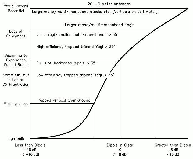
We should note the range across the bottom of the chart. My best estimate is that from –5 dBi to +13 dBi is the practical range of typical, installed (not in free space) amateur antennas. This represents inefficient verticals up to efficient Yagis at reasonable heights and is shown in the chart in Figure 2. Notice that this range is not all that large: 18 dB; and people with severe antenna restrictions will have a larger difference than 18 dB. If we take the center dipole, moving + or – a few dB makes a noticeable difference in the performance. Yagis and other horizontally polarized antennas receive a benefit from being over ground and will achieve ground reflection gain that can represent about 4 to 5.5 dB of the stated figures. Vertically polarized antennas do not benefit from ground reflection gain and usually lose energy because of the ground (unless it is over salt water).
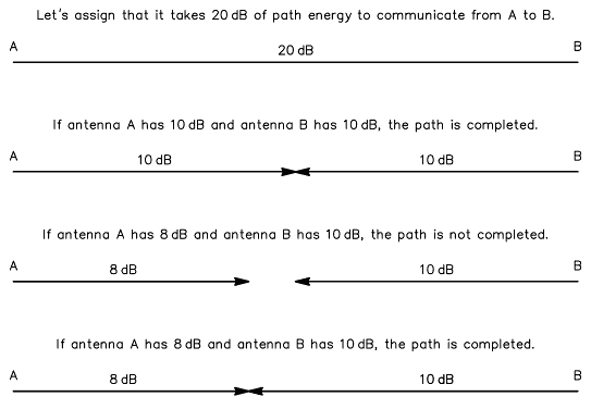
It is important to keep in mind that this chart applies to both ends of the circuit. Oftentimes, a QSO is made because one end has an efficient system that has enough gain at the right angle(s) to overcome the shortcoming of the antenna at the other end and complete the path.
Once we are at a horizontal dipole (in the clear) performance level, we are doing very well and will experience a lot of fun and enjoyment in Amateur Radio. Below this envelope, we will be able to make QSOs, but our understanding of the activity on the air will be limited. If you think you are at this point, try something more efficient! Try something that “works better.”
The charts are not intended to imply it is impossible to enjoy radio with something less than a dipole in the clear. Being able to hear anything and make QSOs can be enjoyable, but this will not necessarily move us along to share more of the enjoy-ment in radio. We should recognize the capability, the performance envelope, of our current antenna system and contemplate if there is another step we can take—just like my history, moving from one antenna to another and making discoveries.
for success at both ends of the path.
How much “better” does the antenna have to be to make how much difference? The chart in Figure 3 is a hypothetical communications path and the relationship between the antennas at both ends.
Translating the charts into practical antenna systems, the following becomes apparent:
| More efficient antenna = expanded performance envelope More efficient antenna = longer operating window to make contacts More efficient antenna = more enjoyment of radio |
Illuminator Antenna
A light bulb. Did someone actually say the left-hand side of the performance chart is a light bulb? Yes, it is. Can it actually “work”? Of course! As I stated in the beginning, everything does work. The difference is the performance envelope.
We gathered one day around a trio of laptop computers, a collection of coffee, soda and water, talking strategy for our contest team (6Y2A, 4M7X). The team leader, Kenny Silverman, K2KW shared some experiences he had many years ago using a light bulb. He was inside a building teaching code and using transceivers with light bulbs for dummy loads. He decided to move up into an amateur band and see what he could hear. Sure enough, he was able to make a couple QSOs on 20 meters. We all laughed at the incident and it was obvious an indoor light bulb had to be the worst antenna anyone could ever use.
In preparing Figure 1, we decided to select the light bulb for the left-hand side of the performance chart. QST Senior Assistant Technical Editor Dean Straw, N6BV, one of the contest team members and antenna collaborator for close to 25 years, agreed that the estimate of –18 dB to a dipole should be about right and proved to be so, at least on 10 meters. Note that the difference between a dipole and the world class performance antenna is much smaller than the difference between the light bulb and the dipole. I am my most staunch critic, so eventually it was time to test the light bulb (aka “The Illuminator”) and see what it could do.
An Illuminating Experience
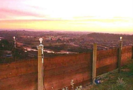
A 150-W bulb was selected for the antenna and a TS-850S transceiver was used. The Illuminator, ah, antenna, um, dummy load was mounted on a porcelain base atop a wooden fence post at a height of about 4 feet. The light bulb is fed through a Force 12 B-1 current balun with 3-inch leads and the feed line was 9913 Flex, to minimize loss. The balun was used to insure the feed line would not radiate. The VSWR of the 150-W bulb was about 4:1 and the built-in tuner matched it easily. I later utilized an external tuner to make small changes as the filament heated up and changed impedance.
The first time The Illuminator was on the air was during the recent 2000 10-10 contest. I operated a total of about an hour. All of the contacts were in the midwest United States. Experimentation showed that if a station moved the S-meter to S-3, I was fairly sure we could make the QSO. Many of the QSOs were made with one call, no repeats, and no comment about how weak the signal was. Interesting. It was obvious that the station on the other end was providing the majority of the necessary system gain to make the path. Nevertheless, it “worked.” I remembered the many times I have heard how well an antenna “works,” because of the number of countries that have been worked. All right, then, maybe we can do even better.
The ARRL DX CW contest was coming. I have operated contests for more than 35 years, but I never felt so ill equipped to call someone. It was mid-morning on Saturday and the wind and rain made it impossible to work outside. I knew it was time to get on the air. I could hear several DX stations running pile-ups. The first station I decided to try was V47KP. I send my call at 36 WPM—he comes right back. One call. Perfect. It was just like using a “real antenna.” Hey, that wasn’t just my first DX with a light bulb, but a new distance record. My sporadic operating using The Illuminator antenna produced 14 countries on 10 meters the first day. I brought the log to the Paso Robles Amateur Radio Club potluck dinner that evening and Larry, W7CB, noticed I was missing Africa for Worked All Continents. Aha – another challenge!
I figured the best bet to work Africa would be if Jim Neiger, ZD8Z, was on because he is using very high gain antennas pointed at the US. The sun had begun to brighten the morning sky and I was tuning across the band with The Illuminator. By the way, the band is really quiet on this antenna. I hear some one. Sure enough, there he is. ZD8Z was having trouble maintaining his frequency and hearing through some European stations. His signal was less than S1 on the meter, so based on experience with The Illuminator, I knew I would have to wait for conditions to improve. About 90 minutes later the sun was fully up, and so was ZD8Z, reaching S3/S4 on peaks. It took a few calls, but we made it: the first Worked All Continents on a light bulb. Now I was really motivated, but there was more work to be done outside before the next rain. I decided that short rest periods were necessary every hour. With casual operating, the country count at the end of the contest was 28, with 41 stations worked.
To date, the farthest QSO on 10 meters was with ZD8Z… all with a barefoot powered light bulb from California. To peg The Illuminator to other antennas you might have experienced, there have been only two stations whose signals reached S6-S7 on the meter, which pushes at least S9+25 signal on a 5-element monoband Yagi. The typical signal level required for contact runs between S1 and S3 on the meter, measuring about S9+10 on the Yagi. Occasionally, success with signals reading less than S1 is possible and is most assuredly due to an effective antenna system and quiet location on the other end. The obvious moral here is that if you do not hear many strong signals, the antenna system is not very efficient.
Shedding Light
Achieving Worked All Continents in a few hours with a light bulb clearly sheds light on the idea that “everything works.” Putting the performance envelope in the spotlight is the important message of this experiment. Although I had fun using the light bulb, it certainly would not promote my interest in Amateur Radio if it were my only antenna. Adding a kilowatt amplifier would allow more QSOs to be made, but I would not hear any better. If I only had one (poor) antenna at my house, I would not be aware of the sea of activity on our bands. If I had two antennas, one would always work better and I would quickly discover the difference between their performance envelopes.
The more efficient your antenna, the more QSOs and enjoyment you’ll receive from our wonderful hobby. Looking back to the Figure 2 chart, a dipole in the clear is a very good antenna and having an antenna with the gain of a 2-element Yagi gets us a long way to a potential world-class station.
While everything “works,” some antennas certainly “work” much better than others.