The initial version of Mini-K9AY antenna was published in finnish here. The english translation by Mauno Ritola is here:
Mini-K9AY
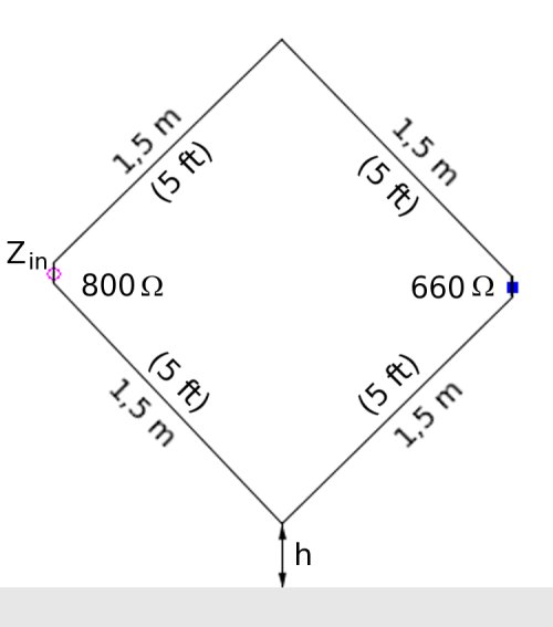
K9AY antenna has triangular shape, height being 7.62 metres and width about 9.3 metres. Mini version of the antenna is much smaller. Height is 1.5 metres and width only 1 metre. To function effectively Mini-K9AY antenna requires terminal resistor (marked as "R" in the picture, with value of 125 - 200 Ohms). The impedance of the antenna is approximately 200 Ohms. The antenna must be connected with 4:1-impedance transformer to 50 Ohm coaxial cable and the receiver. Mini-K9AY antenna works best on medium wave on lower frequencies of shortwave (2.3 - 5.1 MHz). It is fairly effective also on other shortwave frequencies. Mini-K9AY antenna is very suitable for noisy environment: it attenuates nearby noise. The antenna gets it directional properties with its terminating resistor, and adjusting it may be useful to find the least noisy reception. The antenna receives best from the direction of the terminating resistor ("R" in the picture). Amplification of the Mini-K9AY is on medium wave abound -60 dB, and on low parts of SW-35 dB at best. The angle of the receiving beam is ±90°. The arrival angle is 25-30°. The attenuation of the incoming signal from backlobe depends on the value of the terminating resistor and may be 15-25 dB. Since Mini-K9AY has weaker gain than its big brother (on MW about 30 dB and in tropical bands about 10 dB less), I recommend using a good-quality, low-noise preamplifier.
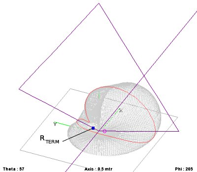
My analysis of a ‘real world’ Mini K9AY is slightly different. I used a ‘ground improvement’ with two wires of 5.9 metre (19 1/4 ft) lying on the ground perpendicularly to the loop plane. The simulation uses a Sommerfeld-Norton ground with dielectric constant of 13 and conductivity of 0.005 mhos/m. The gain of the Mini-K9AY is about -44.4 dB, the main lobe opening angle (-3 dB) is ~90°. The wave angle is 20-40° with a maximum at 34°, the F/B of 27 dB with RDF 7.98 and SWR 1.17 for 450 ohms.

Mini-K9AY, overall view
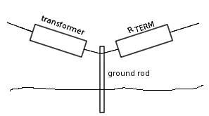
The box containing the termination resistor and transformer
In contrary to the original description, the best F/B at 3525 kHz is achieved with termination resistor of 457 ohms, the transformer ratio should be 1:9.
The null is at the termination resistor side.
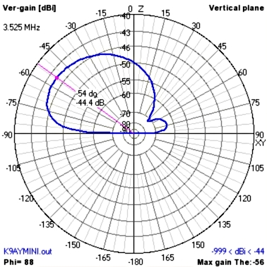
The Mini K9AY radiation patern, vertical plane.
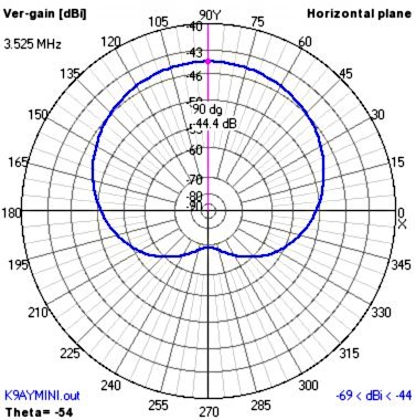
The Mini K9AY radiation patern, horizontal plane.
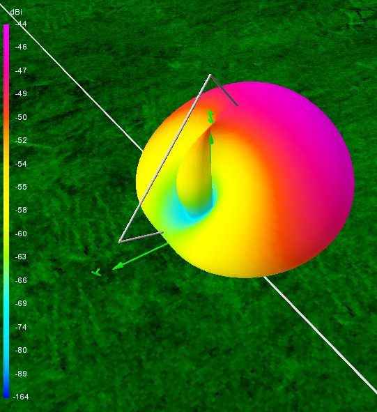
The Mini K9AY radiation patern, 3D view.
Here is the NEC model used:
CM K9AY Loop mini 80 m
CE
GW	1	7	0	0	0.03	0	-0.89	0.27	1.5e-4
GW	2	11	0	-0.89	0.27	0	0	1.5	1.5e-4
GW	3	11	0	0	1.5	0	0.89	0.27	1.5e-4
GW	4	7	0	0.89	0.27	0	0	0.03	1.5e-4
GW	5	11	0	0	0.03	5.9	0	0.03	1.5e-4
GW	6	11	0	0	0.03	-5.9	0	0.03	1.5e-4
GE	0
EK
LD	4	4	7	7	457	0
EX	6	1	1	0	1	0
GN	2	0	0	0	13	0.005
FR	0	1	0	0	3.525	0
160 m
Another analysis at 1825 kHz shows that the results are valid also on 160 m band. The ‘gain’ dropped to -55.3 dB and efficiency to 0.1%, but the RDF is still 7.87 with the same pattern shape and SWR with 1:9 transformer should be 1,09.