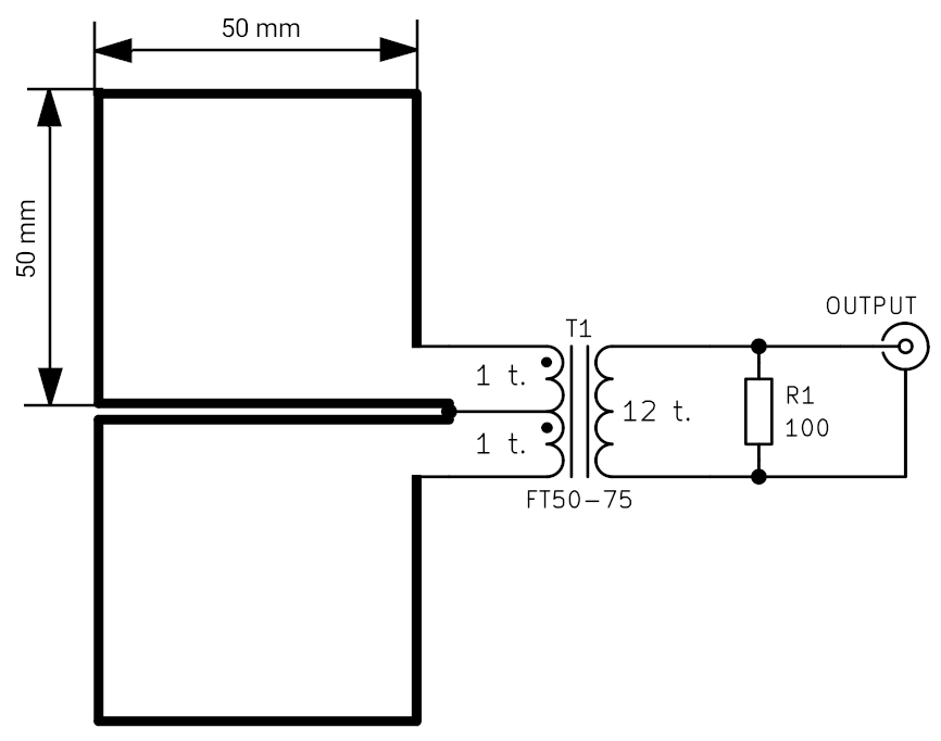
A small dual loop antenna, in other words a differential RF current sensor is shown on the picture below.

(Credits go to Chavdar Levkov, LZ1AQ)
Another image shows my implementation – a compact version, made from PCB with conductors on both sides ’embroidered’ with vias. Gerber data available (download here).

(as output connector use an ‘edge’ SMA)
It is sensitive only to magnetic field component. The electric field common mode leakage is minimized. It has a well pronounced directional pattern with a sharp minimum. The transformer is wound on a FT50-75 toroidal core with 1+1 turn primary and 12 turns secondary winding. For use with high impedance devices the output is loaded with a non-inductive resistor – here a big 4020 size SMD resistor. There is no need to use this resistor if the differential sensor will be used strictly with 50 ohm input impedance devices. I use it connected to my Siglent SDS1202X-E scope or to input of the TinySA Spextrum Analyzer.
This sensor allows to detect the conducting noise current from the shack propagating along the antenna feeders and to test the effectiveness of the baluns. It was used also for detection of the noise generated by switching power supplies.