While browsing my paper archives, I found two folded, together stapled paper sheets with almost unreadable pictures of a control box for the K9AY loop receiving antenna* (a note see below) and a preamp with filtered input which was unreadable at all, however the schematic recalls the already published K9AY design using the 2N5109 CATV transistor.
I can’t remember where I get it, the second paper had a hand-written remark ‘wellbrook? out of production?’ in the corner. The control box allows to switch the direction and to change the termination resistor, so I decided to scan and reconstruct the drawing and PCB design for others who may need it. Also I would like to add a notice of the author where the credits should go. If this construction seems familiar to you, drop me a mail, please.
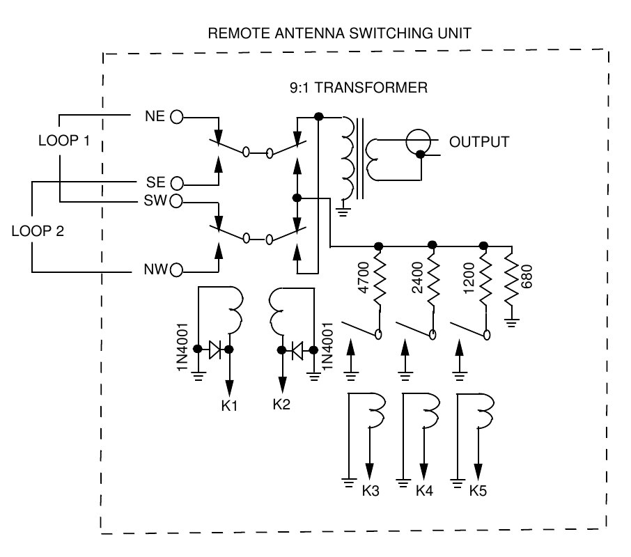
Control box schematic
(click to enlarge)
The control box using an interesting trick with relay switched, paralleled resistors providing 8 values of terminating resistor as follows:
Relay
R1 = 680 (permanent)
R2 = 1200 (K5)
R3 = 2400 (K4)
R4 = 4700 (K3)
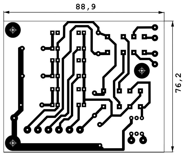
The PCB layout
(dimensions in millimetres)
(left click the image and ‘Save as’ to get a high resolution image,
good for the PCB production – 4.7 MB!)
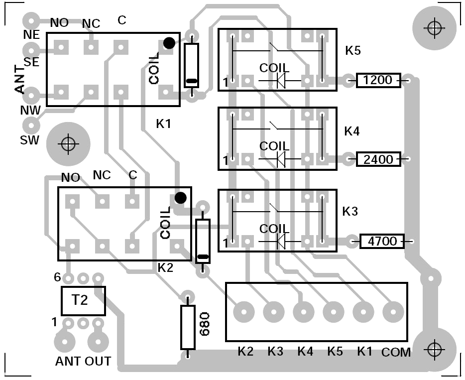
Parts placement
(click to enlarge)
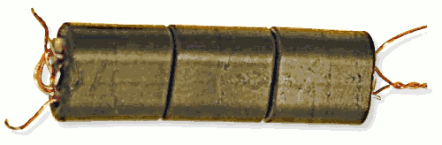
The PC board also holds a transformer 1:9. No details given but I prefer three stacked BN73-202 binocular cores wound in W8JI style with 2 turns on the low impedance side and 6 turns on the antenna side. The results were great, however without a proper ground the K9AY shows rather bad F/B ratio. Anyway, a grounding rod driven to about 4 ft depth plus 4 ‘radials’ of 30 to 60″ improved this antenna significantly.
The preamp is a symmertrical design with two 2N5109s, each draws some 113 mA (therefore needs a heatsink) and the input has a low-pass and high-pass filters in series, forming a bandpass filter (like the original K9AY preamp). It will be described in another article (coming soon).
* (2012-09-08) a friend just told me that this control box came from Far Circuits (see here). Actually, they have PDFs to download with the schematic and PCB layout reconstructed above. So, the credit with kudos (and some apologies) go to Far Circuits!